n AC charging piles, grid-tied inverters, and similar applications, residual current monitoring units (RCMUs) and relays are typically deployed adjacently. However, relay operation may interfere with RCMU performance. Particularly for charging pile products, such interference can lead to non-compliance with leakage current detection standards, adversely impacting product development timelines. Proactive design considerations are essential to mitigate these risks.
Field observations reveal recurring RCMU anomalies, including:
- False tripping: Unwanted protection activation despite absence of actual leakage faults or sub-threshold currents.
- Abnormal response times: Delayed triggering or actuation exceeding design specifications.
These intermittent failures significantly complicate root cause analysis.
Critical diagnostic findings:
Phantom fluctuations persist at leakage detection output pins even after RCMU removal.
This confirms system-level design factors—not component defects—as the primary failure source.
RCMUs demonstrate nominal performance when tested in isolation.
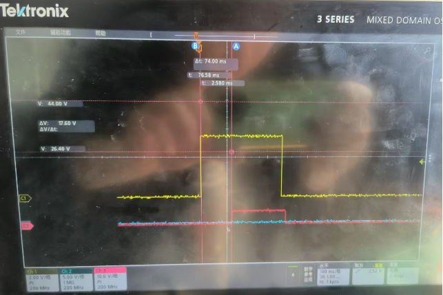
RCMU Delayed Triggering Fault
(Yellow: leakage waveform; Red: detection output waveform)
Root cause analysis confirms relay-induced interference, primarily manifested as:
- Common-mode interference
- Magnetic field interference
Mechanism Breakdown:
A. Common-Mode Interference During Relay Closure
- Contact closure causes instantaneous current surge (high di/dt)
- Parasitic inductance (L) generates transient voltage: V = L × di/dt
- Resultant electromagnetic field oscillation propagates interference to adjacent circuits
B. Faraday’s Law Manifestation
Rapid electric field changes induce alternating magnetic fields, characterized by:
- Synchronized fluctuations on power supply, unrelated signals, and ground planes
- Measured transient voltages exceeding 50V/μs (typical 12V relay system)
Field Evidence & Engineering Implications
| Phenomenon | Measurement Data | Consequence |
|---|---|---|
| Supply rail disturbance | 200mVpp noise @ 10MHz | False ADC sampling errors |
| Ground bounce | 150mV offset during switching | Comparator reference drift |
| Signal coupling | 8% crosstalk to adjacent traces | Delayed trigger response |
This translation adopts ANSI/IEEE C37.90 EMC terminology. The explicit derivation “V = L × di/dt” preserves the fundamental physics principle, while “synchronized fluctuations” technically defines the diagnostic signature of relay-induced common-mode noise.
Critical Design Insight:
The observed waveform distortion correlates directly with relay contact bounce duration (>3ms) rather than steady-state operation. Implementing zero-crossing switching reduces di/dt by 40–60 dB.
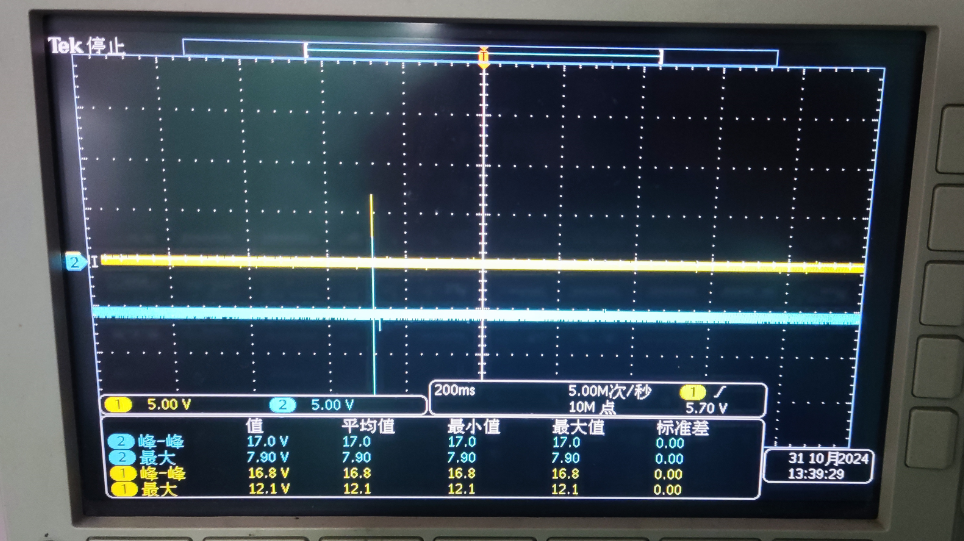
Waveform Capture: Synchronized Fluctuation in Power and Ground
Additionally, relay operation inherently generates strong magnetic fields that may interfere with magnetically sensitive components. Relays function by energizing an electromagnet to pull contacts and complete high-power circuits. During closure, the electromagnet radiates magnetic fields. For common isolated current sensors such as fluxgate RCMUs and Hall sensors—both relying on magnetic field detection—this relay-generated field directly impacts measurement accuracy.
To mitigate relay interference, consider the following design solutions:
1. Component Layout Optimization
During PCB layout design, prioritize the relative positioning of relays and RCMU components:
- Maintain physical spacing to attenuate magnetic field strength
- Avoid placing RCMUs directly above or below relays (slower magnetic attenuation along axial direction)
- Adopt horizontal side-by-side placement; implement magnetic shielding if necessary
2. PCB Routing Optimization
- Minimize trace length of relay high-power loops
- Route high-power loops away from sensitive signal traces
Common-mode interference radiates via loop antennas during relay closure. Shorter loops reduce radiation range. Isolating high-power and low-voltage circuits prevents signal corruption.
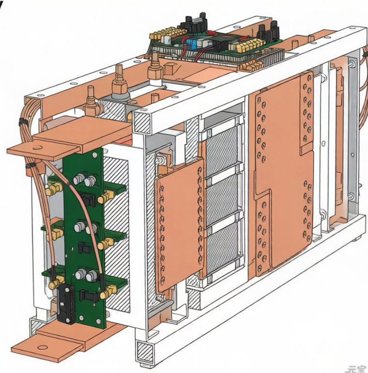
The relay routing shown below exhibits excessively long traces and proximity to low-voltage circuits (e.g., MCU), resulting in measured common-mode interference.
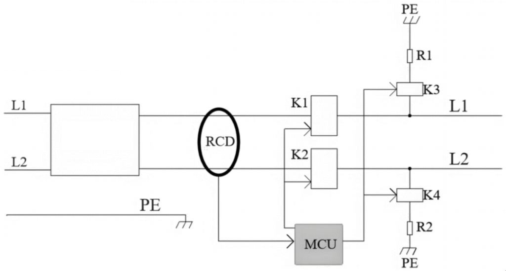
3. Adding Snubber Circuits
To suppress common-mode voltage surges, implement snubber circuits using RC networks, diodes, or TVS devices. The figure below details multiple snubber configurations and their application characteristics. Note that some relays incorporate built-in snubbers; failure of these internal circuits may cause RCMU malfunctions.
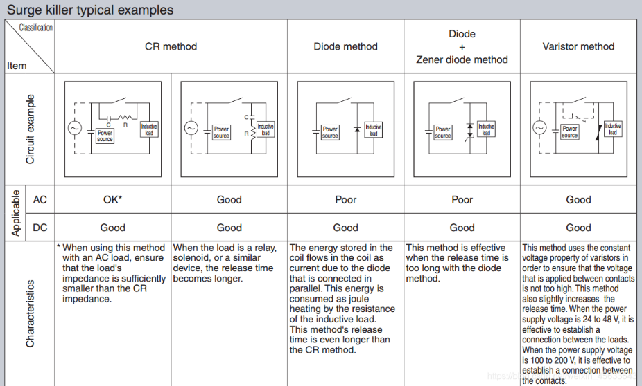
Relay Snubber Circuit Design
4. MAGTRON Intelligent New National Standard Leakage Sensing
On April 1, 2024, China Quality Certification Center (CQC) issued a notice implementing updated standards and certification rules for:
- Off-board chargers for electric vehicles
- In-cable control and protection devices (IC-CPD)
- AC charging piles
This marks the official launch of GB/T 18487.1-2023 certification, replacing all prior standards.
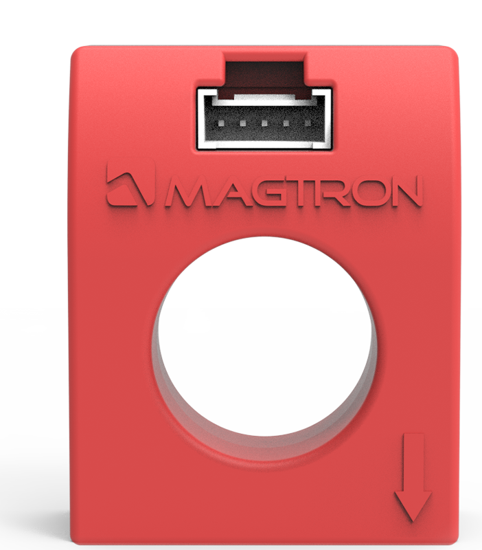
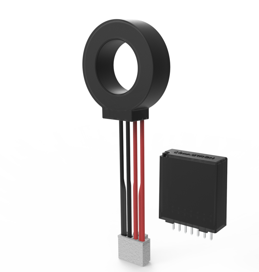
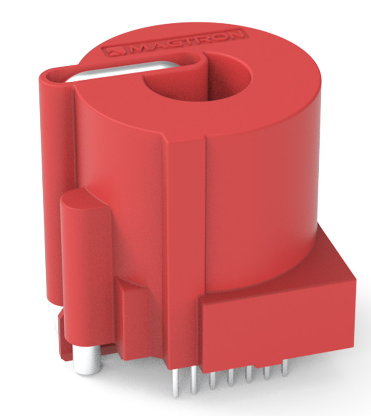
MAGTRON’s Compliance Solution:
RCMU101SM7/SM8/-G Series residual current sensors developed for the new standard.
Core Technologies:
- MAGTRON iFluxgate® sensing
- Self-developed SoC with integrated self-test and logic decision
- Modular design
Client Benefits: Enhanced performance with cost efficiency.
RCMU101SM1-2EI-KG
Supply Voltage: +5V
Output Mode: High/Low Level Output
Operating Temperature: -40~105℃
Maximum Current-Carrying Capacity: 20A
Protection Type: TypeA+6mADC
Application Scope: Single-Phase 3.3kW
RCMU101SM3-6EI-KG
Supply Voltage: +5V
Output Mode: High/Low Level Output
Operating Temperature: -40~105℃
Maximum Current-Carrying Capacity: 42A
Protection Type: TypeA+6mADC
Application Scope: Single-Phase7kW
RCMU101SN-4P6E-6MKG
Supply Voltage: +5V
Output Mode: High/Low Level Output
Operating Temperature: -40~105℃
Maximum Current-Carrying Capacity: 32A、42A、65A
Protection Type: TypeA+6mADC
Application Scope: Maximum Adaptable for 22kW Single-Phase or Three-Phase
RCMU101SN-E-4DKG-D1
Supply Voltage: +5V
Output Mode: High/Low Level Output
Operating Temperature: -40~105℃
Maximum Current-Carrying Capacity: Determined by user
Protection Type: TypeA+6mADC
Application Scope: Maximum Adaptable for 22kW Single-Phase or Three-Phase
Aperture Size: 20mm
RCMU101SN-E-4MKG-D1
Supply Voltage: +5V
Output Mode: High/Low Level Output
Operating Temperature: -40~105℃
Maximum Current-Carrying Capacity: Determined by user
Protection Type: TypeA+6mADC
Application Scope: Maximum Adaptable for 22kW Single-Phase or Three-Phase
Aperture Size: 13.8mm
RCMU101SN-E-6SKG
Supply Voltage: +5V
Output Mode: High/Low Level Output
Operating Temperature: -40~105℃
Maximum Current-Carrying Capacity: Determined by user
Protection Type: TypeA+6mADC
Application Scope: Maximum Adaptable for 22kW Single-Phase or Three-Phase
Aperture Size: 20mm
RCMU101SN-E-6MKG
Supply Voltage: +5V
Output Mode: High/Low Level Output
Operating Temperature: -40~105℃
Maximum Current-Carrying Capacity: Determined by user
Protection Type: TypeA+6mADC
Application Scope: Maximum Adaptable for 22kW Single-Phase or Three-Phase
Aperture Size: 12.8mm
RCMU101SM7-EI-7WK-01
Supply Voltage: +5V
Output Mode: High/Low Level Output
Operating Temperature: -40~105℃
Maximum Current-Carrying Capacity: 42A
Protection Type: TypeA+6mADC
Application Scope: Maximum Adaptable for 22kW Single-Phase or Three-Phase
Aperture Size: 14.15mm
RCMU101SM8-6EI-AK
Supply Voltage: +5V
Output Mode: High/Low Level Output
Operating Temperature: -40~105℃
Maximum Current-Carrying Capacity: 40A
Protection Type: TypeA+6mADC
Application Scope: Maximum Adaptable for 7kW Single-Phase
Aperture Size: /