1.Development Trends of Energy Storage Converters (PCS)
To achieve peak carbon emissions by 2030 and carbon neutrality by 2060, new power generation forms are continuously increasing their share of installed capacity in the power market. As of 2022, China’s wind and photovoltaic generation reached 1.19 trillion kWh—an increase of 207.3 billion kWh over 2021, up 21% year‑on‑year—accounting for 13.8% of total electricity consumption (a 2‑point rise), nearly matching the nationwide residential electricity use.
With wind and solar power generation maturing, and to improve overall system reliability, coordinate flexible resource use, and stabilize consumption, the market has begun to spur energy storage deployment. In 2022, China added 13.30 GW of new energy‑storage installations (a 26.67% year‑on‑year increase), bringing cumulative capacity to 59.40 GW. As globally, pumped storage dominates China’s storage mix, while new energy storage is growing fastest: in 2022 it added 6.90 GW (up 182.07% year‑on‑year), for a total of 12.70 GW.

Figure 1: Bar chart of domestic new energy‑storage installations
Thus, with the global energy‑structure shift and large‑scale renewable deployment, energy storage has become a key power‑system component. As the core of the storage system, the performance and efficiency of the energy‑storage converter (PCS) directly affect the economic benefits and technical feasibility of the entire system.
2.Overview of the Energy Storage Converter (PCS)
The energy storage converter (Power Conversion System, PCS) in an electrochemical storage system is the device that links the battery system with the grid (and/or loads) to perform bidirectional power conversion. It controls the battery’s charging and discharging processes, converts between AC and DC, and—when the grid is unavailable—can directly supply AC loads.
A PCS comprises a bidirectional DC/AC converter, a control unit, and other components. The PCS controller receives control commands from the backend via communication interfaces and, based on the sign and magnitude of the power command, drives the converter to charge or discharge the battery, thereby regulating both active and reactive power to the grid. The PCS can also obtain battery‑pack status information through CAN‑bus communication or dry‑contact signals with the BMS, enabling protective charge/discharge management to ensure safe battery operation.
3.Topology Structures of Energy Storage Converters (PCS)
The topology of a PCS determines its conversion efficiency and reliability. PCS architectures are classified into single‑stage and two‑stage structures.
(1) Single‑stage topology
The single‑stage PCS, shown in Figure 3, consists of a single DC/AC stage (a PWM converter). In discharge mode, the battery’s stored DC energy is inverted by the PWM inverter into AC and fed back to the grid. In charge mode, the grid’s AC is rectified by the same PWM converter into DC and stored in the battery.
The PWM converter switches between rectification and inversion to enable bidirectional power flow. Battery cells are arranged in series and/or parallel to meet the converter’s voltage and current requirements.
Advantages: High efficiency, simple structure, low losses, and easy control.
Drawbacks: Limited flexibility in system capacity configuration and a narrow battery voltage operating range.
(2) Two‑stage topology
The two‑stage PCS, shown in Figure 4, comprises a bidirectional DC/DC converter followed by a PWM DC/AC converter. During discharge, the battery’s DC is first boosted by the DC/DC stage, then inverted to AC by the PWM converter for the grid. During charge, the grid’s AC is rectified by the PWM stage, and the resulting DC is stepped down by the DC/DC converter to charge the battery.
For battery configurations of series‑then‑parallel or parallel‑then‑series, a single‑stage converter may suffice. For a series‑then‑parallel arrangement, however, a two‑stage design is often preferred: each series string is connected through its own bidirectional DC/DC module to a common DC bus, which feeds the DC/AC stage, as illustrated in Figure 5.
This topology allows multiple battery strings to operate independently—each with its own DC/DC stage—enabling flexible capacity scaling, independent charge/discharge control, and wide battery‑voltage ranges without inter‑string circulating currents. It also facilitates system management.
Advantages: Flexible capacity and battery‑string management.
Drawbacks: Double energy‑conversion stages increase losses and complexity; coordinating DC/DC and DC/AC stages under different charge/discharge conditions raises control difficulty and can reduce reliability.
Topology can also be classified by voltage‑level count: two‑level vs. multilevel. The most common multilevel variant is the three‑level circuit.
Two‑level circuit topology

shows the classic three‑phase, two‑level bridge topology widely used in PWM converters. Each phase voltage switches between +Ud and –Ud. To improve waveform quality, switching frequency must be increased—at the cost of higher device losses and reduced overall efficiency—motivating interest in multilevel solutions.
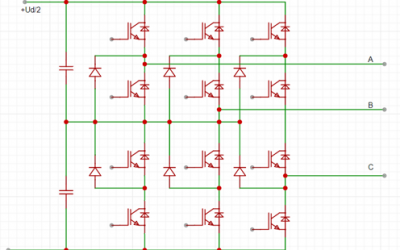
Three‑level circuit topology
In high‑voltage applications, three‑level topologies—especially the Neutral‑Point‑Clamped (NPC) type—are prevalent due to their simplicity and practicality. Compared to two‑level converters, three‑level circuits add a neutral‑point (0 V) midpoint, offering higher DC‑voltage utilization, lower harmonic content, better voltage quality, and smaller filters. Lower switching frequency reduces EMI and improves system efficiency.

illustrates the diode‑clamped NPC three‑level topology. The DC‑side bus comprises two series capacitors (C1, C2). Each leg has four IGBTs, four freewheeling diodes, and two clamping diodes that equalize voltage stress across the IGBTs. The capacitor midpoint ties to the diodes’ midpoint, enabling each phase to output +Ud/2, 0, or –Ud/2.
4.Current Detection Technology
Current measurement is a critical PCS technology, affecting control precision and system stability. Common techniques include resistive (shunt) sampling and Hall‑effect sensors.
In practice, Zhejiang Juci’s CSM series current sensors—based on their proprietary iFluxgate® technology—offer high accuracy, low temperature drift, minimal heating, fast response, and modular design. CE and RoHS certified, they accurately measure charge/discharge currents, optimize traditional charging methods, extend battery life, and save energy. These sensors suit battery management (SOC, SOE, SOF, etc.), pure‑electric and plug‑in hybrid vehicles, and energy‑storage equipment (e.g., EV PACK, BMS, BDU, PDU). We warmly invite all esteemed users to explore our products.
References
- Meng Shun. Research on the Design and Control of Integrated Energy Storage Devices [D]. Beijing Jiaotong University, 2016.
- Gui Yu. Research and System Development of Bidirectional Balancing Control Strategy for Lithium‑Power Battery Packs in Pure Electric Vehicles [D]. Jilin University, 2014.
- Zhang Xingang; Wang Xiao; An Yu; Zhang Yang; Fan Ruixiang. “A Novel Topology of Pulsating‑Output High‑Power Cascaded Energy Storage Converter.” Jiangxi Electric Power, 2022, 46(02): 11–16.
- Shen Xinxin; Zhao Lian. “Analysis of High‑Power Energy Storage Converters.” Applied Energy Technology, 2022, (01): 21–23.
- Zhu Menglong. Research on Key Technologies and Device Development of T‑Type Three‑Level Energy Storage Converters [D]. Shandong Jianzhu University, 2020. DOI:10.27273/d.cnki.gsajc.2020.000190.