In photovoltaic inverters and energy storage conversion systems, when there is abnormal jitter, unstable zero point, or inconsistent performance of different machines in current measurement, the problem is often first attributed to sensor accuracy or device consistency. However, in multiple on-site problem analyses, a less intuitive but frequently occurring influencing factor gradually emerged – common mode voltage level and system grounding method.
This problem is not caused by the failure of a specific device, but by the combined effect of system structure, electrical topology, and sensor working mechanism.
1、 The simulated environment in real applications is far more complex than imagined
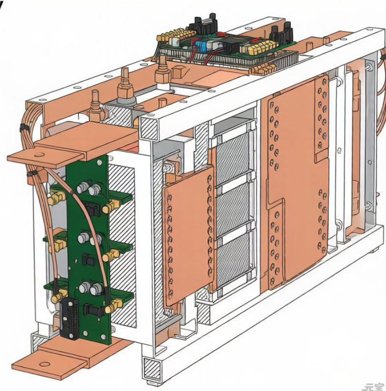
In photovoltaic systems, current sensors typically operate in high common mode voltage environments. For example, on the DC side and inside the inverter, the potential of the primary circuit may be several hundred volts or even higher relative to the control ground. At the same time, the high dv/dt switching behavior brought by wide bandgap devices such as SiC results in rapid changes in common mode voltage.
In laboratory testing, sensors often operate under ideal grounding conditions with limited changes in common mode voltage; However, in practical devices, the grounding path is complex, and there is a potential difference between the protective ground, signal ground, and power ground, resulting in dynamic changes in the common mode environment. This difference is the root cause of many “normal laboratory, abnormal machine” problems.
2、 How common mode voltage affects current measurement
In principle, current sensors measure magnetic fields or compensating currents, but their output signals still need to be transmitted and processed through electronic circuits. When the common mode voltage is high or changes dramatically, the following effects gradually become apparent:
Firstly, common mode interference enters the signal link through parasitic capacitance coupling. Parasitic capacitance is inevitable between the internal detection circuit, power supply circuit, and housing of the sensor. Under high dv/dt conditions, common mode voltage changes will couple through these paths and superimpose on the measurement signal, resulting in high-frequency noise or baseline drift.
Secondly, inconsistent grounding methods amplify the problem of zero instability. In different devices or installation environments, if there are differences in the connection method between the control ground and the power ground, even if the same type of sensor is used, the output zero point may still experience systematic offset. This offset is particularly pronounced under low current or no-load conditions, and is easily mistaken for sensor body drift.
In addition, in multi-channel parallel measurement scenarios, common mode voltage differences may also lead to a decrease in measurement consistency between channels, making it difficult for the system to make effective comparisons and diagnoses.
3、 Why is the problem more prominent under low current conditions
During high current operation, the amplitude of the measured signal itself is relatively large, and the proportion of common mode interference is relatively limited; Under low current or no-load conditions, the signal amplitude decreases, and the proportion of common mode noise and ground potential fluctuations in the measurement results rapidly increases.
Photovoltaic systems operate for a long time in early morning, evening, and low light conditions. If the current measurement is unstable under these conditions, it will directly affect MPPT judgment, standby strategy, and operation status evaluation, and even cause unnecessary protection actions.
4、 Engineering response strategy: returning from “sensor issues” to “system issues”
To address common mode voltage and grounding issues, simply replacing sensor models often has limited effectiveness. A more effective approach should start from the system level: clarifying the connection logic of power ground, signal ground, and protective ground to avoid multiple uncontrolled grounding points; Shorten the length of the sensor signal circuit and reduce the common mode coupling path; Select sensor technology routes with stronger common mode rejection capability at key measurement points; Introduce high dv/dt working condition testing during the prototype stage to expose potential issues in advance.
By verifying the current measurement in a real common mode environment, rather than evaluating it only under ideal conditions, its engineering applicability can be more accurately determined.
Conclusion
In photovoltaic systems, the measurement performance of current sensors is not solely determined by device parameters. The common mode voltage level and grounding method, as a systemic factor, often continue to affect measurement stability during long-term operation. Only by starting from the system structure and understanding the real electrical environment in which current measurement is conducted can reliable and trustworthy current data be obtained under complex operating conditions. This is an essential aspect in the design of highly reliable photovoltaic systems that cannot be ignored.