Skip to content
1.Inverter Grid-Connection Impact Mechanism
During the instant of grid synchronization in photovoltaic (PV) systems, grid-connected inverters frequently generate short-duration inrush currents. This phenomenon directly compromises grid stability and power quality, severely undermining inverter reliability. The core mechanism originates from transient deviations in output voltage versus grid voltage (amplitude, phase, or frequency) during synchronization, coupled with rapid charge-discharge dynamics of DC-side filter capacitors. Furthermore, the interaction between high-frequency switching of power electronics and grid impedance parameters intensifies the pulsed characteristics of transient currents.
The prevalent limitations in surge withstand capability among existing devices have become a critical bottleneck for system reliability—industry data indicates approximately 32% of inverter failures stem from component-level damage caused by grid-connection impacts. Against this backdrop, breakthroughs in RCMU devices’ impact resistance are delivering enhanced solutions for the industry.
2.Surge Failure Manifestations and Model-Based Analysis
2.1 Description of Actual Grid-Connection Impact Phenomena
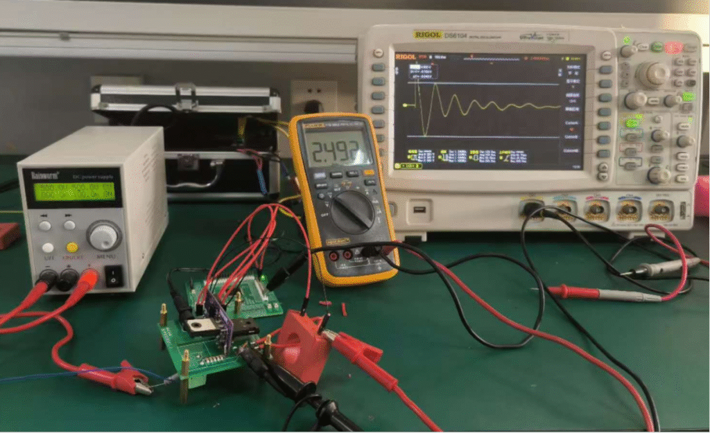
The waveform of inrush current captured during inverter grid synchronization at a client site is shown below.
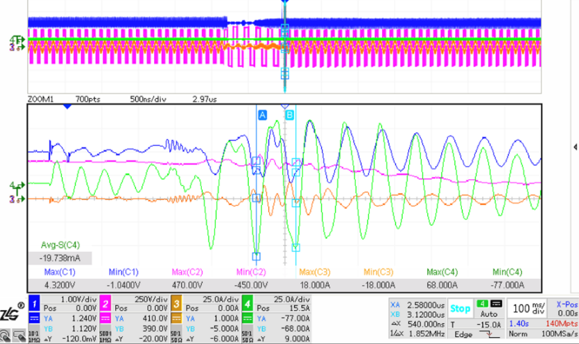
Actual Inrush Current Waveform
In this waveform, the CH4 channel displays the grid-connection inrush current manifesting as a decaying resonant current. This current exhibits:
- Peak value: 77 A
- Resonant frequency: 1.852 MHz
At the oscillation onset, the inrush current demonstrates an extremely high di/dt. According to Faraday’s Law of Electromagnetic Induction, such rapid electric field variation induces a strong magnetic field in conductors, subsequently converting into induced voltage capable of damaging components within the product.

In the equation:
- i₁ represents the inrush current,
- V₂ denotes the induced voltage within the device,
- M is the equivalent mutual inductance between the grid-connection line and the device’s internal circuit.
Devices containing magnetic components and positioned in close proximity to grid-connection lines exhibit higher mutual inductance (M). These components—such as RCMUs and relays—are most vulnerable to damage during grid-connection impacts. User reports confirm frequent failures of output-side relays and RCMU devices in inverters caused by such surges.
2.2 Transient Equivalent Circuit Model Analysis of Grid-Connection Surge
Considering the circuit conditions at the inverter output side and grid during grid synchronization. At the synchronization instant, the control system’s response speed is insufficient to align the inverter output voltage in phase with the grid, resulting in a phase difference. This effectively applies a step-function surge to the circuit. The inverter’s output filter and parasitic inductance in the lines collectively form a series LC configuration, generating resonant currents under this surge. The equivalent circuit during grid-connection surge comprises L, C, and an equivalent surge voltage source.

Circuit Analysis and Equivalent Model
When a voltage source produces a step signal of magnitude V at time *t* = 0, the surge current is given by:

This expression manifests as a gradually decaying sinusoidal resonant signal with a resonant frequency of:

The peak value of the resonant circuit is:

The surge current expression derived from this equivalent model aligns with actual waveform measurements. Evaluating worst-case scenarios using this expression reveals that the surge intensity peaks when the step voltage amplitude is maximized—occurring during complete phase opposition between the inverter and grid (≈440V). The resonant frequency corresponds to that of the equivalent LC circuit, while a higher **C/L ratio amplifies the surge peak value.
Consequently, applying a step-function surge to a specific series LC circuit can effectively simulate the grid-connection inrush current of inverters.
3.Surge-Induced Failure Simulation and Surge Withstand Test
3.1 Circuit Simulation Assessment
First, construct the circuit model in LTspice to simulate the surge current. Designating:
- Switch at voltage source V1 side as S1
- Switch between L and C as S2
The circuit operates in two modes:
- Mode 1: S1 ON / S2 OFF → V1 charges C1 to 400V
- Mode 2: S2 turns ON instantaneously while S1 turns OFF → C1 discharges into the RLC circuit
To achieve sufficiently high resonant frequency, C1 must be minimized. However, this results in rapid voltage collapse due to discharge loops formed by its equivalent parallel resistance (EPR). Consequently, S1 and S2 must employ power semiconductor devices with switching speeds one order of magnitude faster than the discharge time to negate capacitor leakage effects.
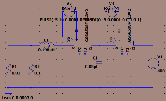
Simulation Circuit
The LTspice circuit simulation results are shown in the figure below. Both the capacitor and GaN HEMT employ high-fidelity SPICE models of actual components, incorporating parasitic parameter effects. The simulation waveform reveals a resonant current peak of 92 A and a resonant frequency of 1.607 MHz, indicating that the circuit under these parameters generally meets the design specifications.
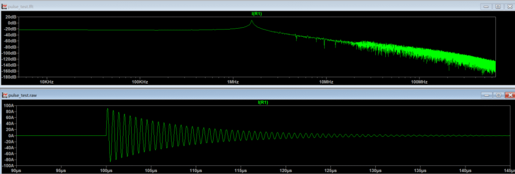
Simulation Waveform
3.2 Analog Circuit Testing
To accurately simulate grid-connection surges in inverters and validate Magtron’s RCMU products’ capability to operate reliably under such conditions, a physical test circuit was constructed to replicate this operating scenario. RCMU series products were connected in series within the circuit. The peak surge current was regulated by adjusting the output voltage of a high-voltage power supply.
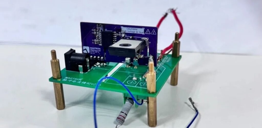
Surge Simulation Circuit
During actual testing, the power supply was set to a maximum of 500V (constrained by the switches’ 600V withstand voltage rating). This configuration simulated a surge current peak of 98.4 A and a resonant frequency of 1.33 MHz, effectively replicating real-world grid-connection surge conditions.
Test Execution:
- Two RCMU models were selected
- Three units per model tested (*n* = 3 × 2)
Result:
Both Magtron RCMU products remained fully operational under this surge regime, validating their robust surge withstand capability against inverter grid-synchronization impacts.
RCMU series
4.Technical Recommendations for Mitigating Inverter Grid-Connection Surge Impacts
1. Select components with superior surge withstand capability.
Validated through testing, Magtron RCMU series products maintain reliable and accurate operation during grid-connection surges, withstanding >50 kA under 8/20 μs surge tests. This meets the operational demands of grid-tied inverters in real-world harsh conditions.
2. Implement grid pre-synchronization technology.
The root cause of grid-connection surges lies in the instantaneous phase difference between inverter output voltage and grid voltage at synchronization. Research indicates that deploying grid-side voltage sensors to achieve phase synchronization before grid connection effectively eliminates phase misalignment transients.
3. Optimize output filter parameters.
As demonstrated by the equivalent circuit model, surge current characteristics are governed by the LC circuit parameters primarily determined by the output filter. While maintaining filtering and EMC compliance, adjusting filter L/C values enables control over:
Ringing frequency
thereby reducing surge impact severity.
Maximum surge current amplitude