Skip to content
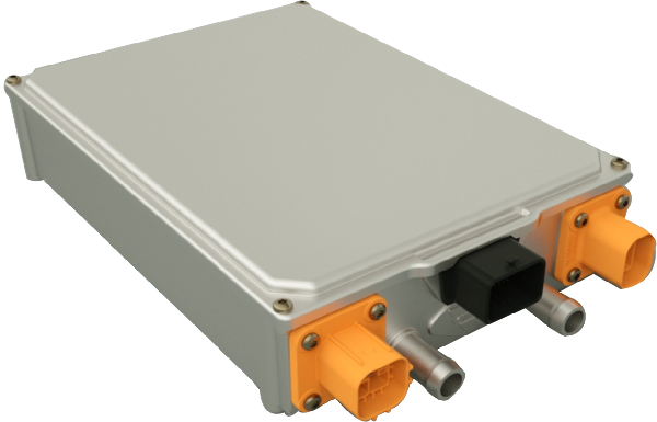
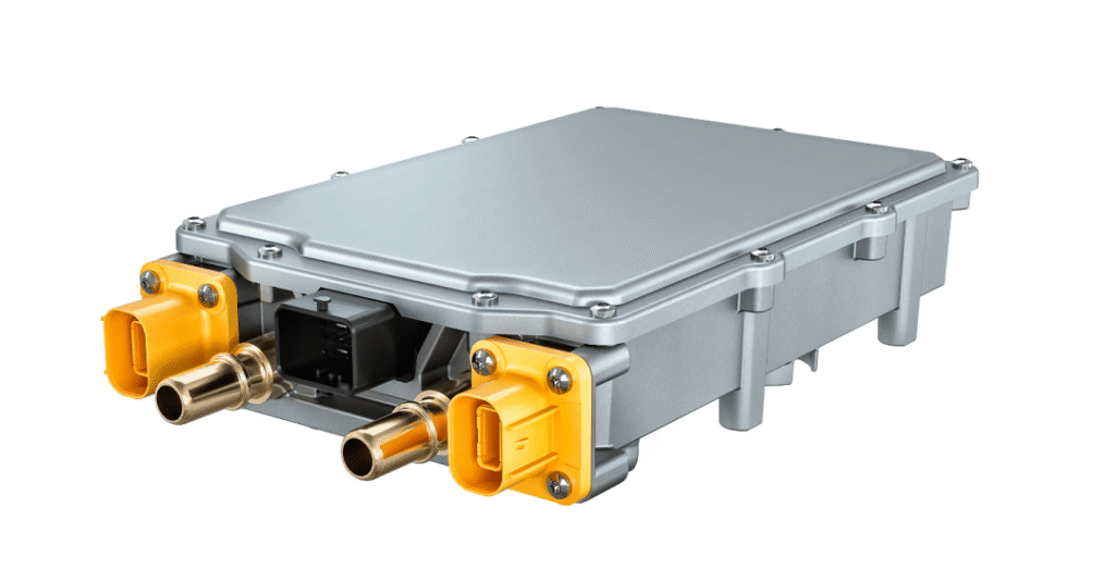
The On-Board Charger (OBC) is an interface component of Electric Vehicles (EVs). It must interact externally through connections to either the public grid or dedicated EV supply equipment. These devices interface with the AC grid, and their ratings and requirements fall outside the manufacturer’s control. Consequently, any vehicle equipped with a built-in charger must comply with specific regulations to be marketable.
1.Power Quality
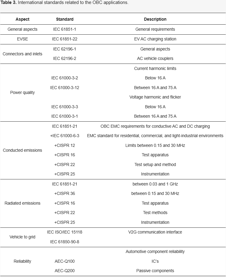
For low-voltage equipment, the IEC 61000-3-2 standard must be followed. Battery chargers are classified as Class A under this standard, which covers all electrical equipment (single-phase and three-phase) rated at 16A or less (corresponding to Mode 1 charging) and connected to the low-voltage grid side. For higher current levels, the reference standard is IEC 61000-3-12, applicable to electrical equipment rated above 16A but not exceeding 75A, thus covering the other two charging modes: Mode 2 and Mode 3.
Voltage harmonics and flicker caused by the interconnection of OBC chargers are regulated according to IEC 61000-3-3 and IEC 61000-3-11.
The aforementioned IEC power quality standards primarily focus on low-frequency harmonics up to the 40th order. However, advanced power electronic converters featuring high switching frequencies and low frequency distortion extend the frequency range beyond the typical 40th harmonic limit, reaching into the 2 kHz to 150 kHz band – i.e., exceeding the general harmonic range. Although this phenomenon is not currently addressed in the present version of IEC 61851-1 (2019), it has attracted attention within the industry, as evidenced by standards like IEC 61000-2-2:2017.
2.Battery Pack Requirements
Strict size limitations are imposed on OBCs during vehicle charging due to battery pack system evaluations. Furthermore, GaN-based high-frequency switching designs in OBCs generate superimposed high-frequency ripple currents on the battery system. Research indicates that batteries degrade faster under charge/discharge cycles with current ripple.
One study examined the long-term aging effects of superimposed current ripple (55Hz to 20kHz) on 18650-type cells. Results showed that under identical cycle counts and ripple current magnitudes:
- Cells exposed to the highest frequency ripple exhibited greater temperature rise than other samples.
- Battery Management System (BMS) protection mechanisms (response time: 10–100 ms) cannot activate voltage protection promptly against transient overcharge/over-discharge when ripple frequencies exceed 100 Hz–1 kHz.
While no specific requirements exist in literature, studies suggest methods to enhance battery system reliability:
(a) Maintain ripple current <5% of rated current at frequencies >1 kHz
(b) Implement independent AC/DC conversion to reduce DC charge/discharge ripple content
(c) Minimize ripple current superposition in battery stacks (e.g., 96-cell pack shown in Fig. 1a/1b) across all CC/CV charge/discharge modes. Given lithium-ion batteries’ (LIB) susceptibility to lithium plating, reducing both charging current and ripple is critical—especially at high State-of-Charge (SoC).
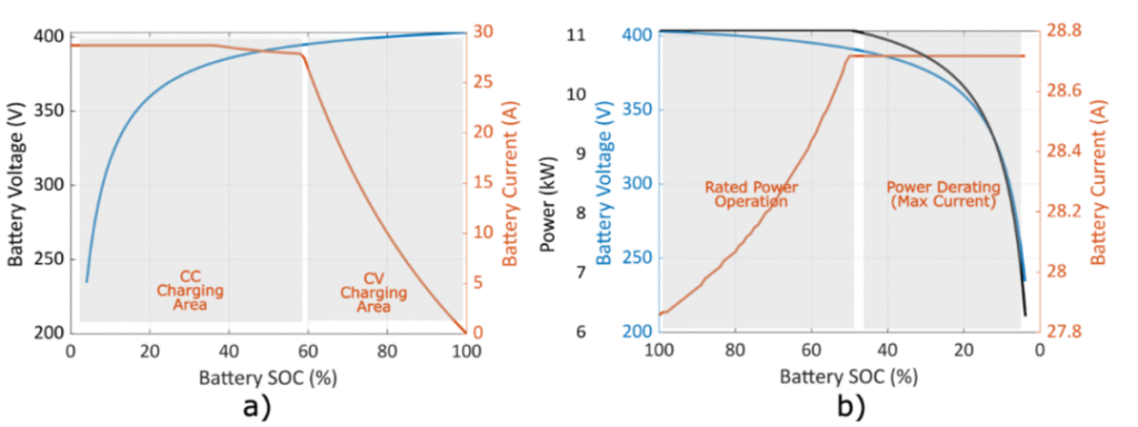
Fig. 1. Typical battery current and voltage waveforms: (a) G2V, (b) V2G
3.Electromagnetic Compatibility (EMC)
The operational characteristics of switching power supplies – featuring high switching currents and steep voltage transitions – inherently generate electromagnetic emissions. These emissions propagate either through:
- Conductors (conducted emissions: 150 kHz – 30 MHz)
- Air (radiated emissions: 30 MHz – 1 GHz)
potentially causing electromagnetic interference (EMI) with nearby equipment.
Standard Compliance
The IEC 61851-21-1 standard defines EMC requirements for conductive connections between:
- Electric Vehicle On-Board Chargers (OBCs)
- AC/DC power supplies
adopting test methodologies from the International Special Committee on Radio Interference (CISPR). This standard applies to:
Electronic/electrical sub-assemblies intended for vehicle use
Complete vehicles
3.1 Conducted Emissions
IEC 61851-21-1 defines measurement techniques and conducted emission limits on AC or DC power lines. These guidelines distinguish between Class A (residential) and Class B (light industrial) environments, setting peak and quasi-peak limits for conducted emissions. As automotive electronics, the limits defined in CISPR 25 and IEC 61000-6-3 form the basis for OBC design applications. Conformance testing for conducted emissions also relies on the test methods, setups, and correction factors described in CISPR 12, CISPR 16, and the superseded CISPR 36. Although conducted emissions can be minimized through modulation schemes and soft-switching techniques, EMI filter circuits remain essential.
3.2 Radiated Emissions
Beyond the fundamental requirements defined in CISPR 12, CISPR 36 was developed to establish a radiated emission standard covering the 150 kHz to 30 MHz frequency range for vehicles (excluding mild hybrid vehicles). Electric vehicles often generate radiated emissions in low-frequency bands not covered by CISPR 12 (which protects external receivers at 10-meter distances for the 30 MHz to 1000 MHz range). To comply with radiated interference requirements, GaN-based OBC designs demand maximum layout optimization to minimize emissions caused by high dv/dt switching transients.
4.V2G Functionality and Safety
Although bidirectional charging technology exists, current standards addressing bidirectional OBCs remain limited.
IEC 61851-1 describes the minimum safety requirements for electric vehicle supply equipment with rated supply voltages below 1 kV. These include:
- Access protection (IP)
- Creepage and clearance distances
- Temperature rise limits
- Electric shock protection
- Protective circuit integrity
- Connection protocols
- Overload and short-circuit protection
For touch current and residual current limitations, OBCs must strictly comply with thresholds defined in IEC 61140. The limit for current passing between any AC interface and the vehicle chassis is 3.5 mA (rms) at 50 Hz. UL 2202 imposes stricter restrictions than IEC 61851, limiting leakage current to 0.75 mA (rms) for Class 1 equipment.
Finally, literature discusses non-isolated charger topologies. However, their implementation faces significant challenges, primarily due to leakage current generation and associated risks to humans and surrounding equipment.
The IEC standard limits leakage or residual current to 30 mA, monitored by EV supply equipment. Inevitably, most advanced OBC designs adopt isolated converter topologies as they provide a less challenging way to meet stringent standard requirements and mitigate false tripping caused by common-mode currents.
In 2024, the International Organization for Standardization published ISO 5474-2: Electrically propelled road vehicles — Functional and safety requirements for power transfer between vehicle and external electric circuit — Part 2: AC power transfer. This standard specifies requirements for conductive AC power transfer (up to 1000 V AC) between electrically propelled road vehicles and external circuits. It also defines requirements for conductive charging (Modes 2, 3) and reverse power transfer according to IEC 61851-1.
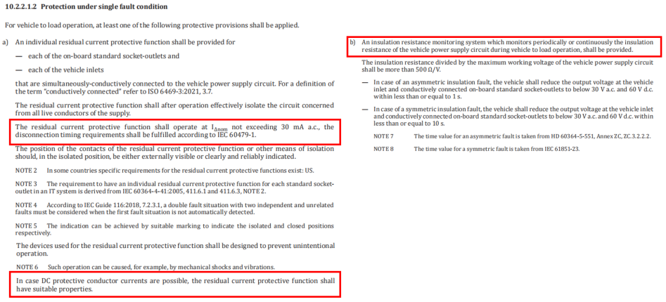
Protection requirements under single-fault conditions:
When the vehicle is connected to a load for operation, at least one of the following protections must be applied:
(a) A dedicated residual current protection (RCD) function shall be provided. Each onboard standard power socket or vehicle-side charging port requires independent leakage current protection.
Leakage current detection: Must detect ≥30 mA AC. If DC exists in the system, DC leakage detection is mandatory.
(b) An insulation resistance monitoring system (IRMS) shall be provided. This system periodically or continuously monitors the insulation resistance of the vehicle’s power circuit during all operational phases.
5.Reliability
A primary focus in the electric vehicle transition includes user experience, driving range, safety, battery lifespan, charging time, control robustness, and aging. Component stress and lifespan qualification primarily follow the automotive industry’s Automotive Electronics Council (AEC) Q100-Q200 standards. AEC-Q100 (for ICs) and Q200 (for passive components) define four qualification grades, specifying environmental conditions (e.g., temperatures and humidity levels) depending on the device’s location within the vehicle.
Magtron employs its proprietary patented iFluxgate technology to deliver cost-effective current sensors featuring ultra-low zero drift and high bandwidth, enabling high-precision current acquisition. The company’s self-developed SoC chips further provide customized technical solutions. Continuously upgraded to address evolving market demands, these innovations resolve critical current and leakage current monitoring challenges across industrial, electric vehicle, and energy storage applications, ensuring robust electrical safety for power equipment.