At the moment a PV inverter is connected to the grid, it is often accompanied by a brief yet intense current pulse—known as the grid-connected inrush current. Though lasting only milliseconds, this phenomenon harbors enormous energy capable of damaging core components, making it an “invisible killer” that undermines the long-term reliability of PV systems. As PV power plant scales expand and grid interactions grow increasingly complex, problems such as relay adhesion, fuse blowout, and even sensor failure caused by inrush currents have become frequent. The crude traditional “overcurrent protection” model can no longer meet the demands. This article delves into the physical nature of grid-connected inrush, uncovers its unique challenges to current sensing, and explores new precision protection approaches ranging from component selection to system synergy.
I. Grid-Connected Inrush: More Than Just “Excessive Current”
The root cause of grid-connected inrush lies in the instantaneous deviations in amplitude, phase, or frequency between the inverter’s output voltage and the grid voltage at the moment of connection. This deviation is equivalent to suddenly applying a voltage step excitation to the output filter network (inductive L and capacitive C components). The resonant circuit composed of inductors and parasitic parameters is activated, generating a high-frequency damped oscillating current.
Key characteristics amplify its hazards: Extremely high di/dt: Measurements and simulations show that the rise rate of inrush current is exceptionally fast, with di/dt reaching tens of A/μs or even higher. According to Faraday’s Law of Electromagnetic Induction, such rapid current changes induce strong interference voltages in adjacent circuits.
High-frequency oscillation: The oscillation frequency can reach 1-2 MHz, far exceeding the power frequency and conventional switching frequencies. This frequency band is precisely at or beyond the attenuation edge of the bandwidth of many current sensors, potentially causing nonlinearity and delayed responses in sensors.
Significant peak current: Under extreme phase mismatch conditions, the peak inrush current can reach several times the rated current. Though short-lived, the energy is concentrated at the peak.
II. Unique Challenges of Inrush Current to Current Sensors
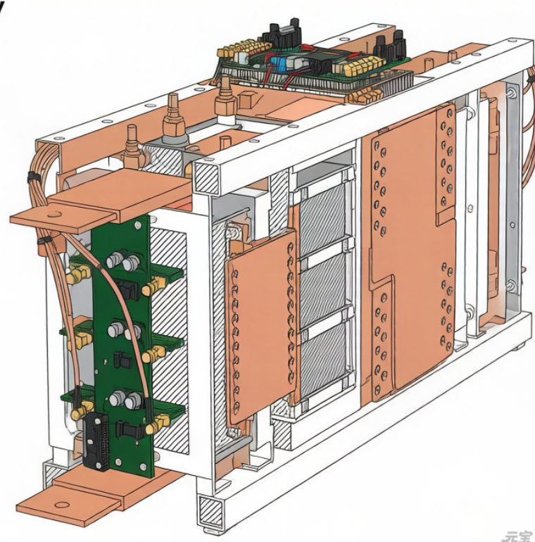
As the “sentinels” of grid-connected current, current sensors bear the brunt of inrush currents. The challenges posed go far beyond simple overload:
1. Risk of Core Magnetic Saturation
For sensors based on magnetic induction principles—such as Hall effect and fluxgate sensors—transient ultra-large currents can cause immediate magnetic core saturation. Once saturated, the sensor temporarily loses its measurement capability, resulting in distorted or zero output. Saturation during the inrush period may lead the control system to misjudge “current loss,” thereby missing the critical window for protection decisions.
2. Trade-off Between High-Frequency Response and Bandwidth
The main energy of inrush current is concentrated at its oscillation frequency. If the sensor’s -3dB bandwidth is insufficient to cover this frequency, it cannot accurately reproduce the true waveform and peak value of the inrush current. This causes the backend protection circuit to make judgments based on attenuated signals, leading to delayed responses. However, blindly pursuing ultra-high bandwidth introduces more high-frequency noise into the control system, increasing instability risks.
3. Common Mode Interference Exacerbates the Issue
The path of inrush current generates a strong time-varying spatial magnetic field, which couples to the sensor’s own signal loop or reference ground through mutual inductance. For sensors with insufficient Common Mode Rejection Ratio (CMRR), this coupled interference directly superimposes on the output signal, forming severe measurement glitches that may be misidentified as a sustained overcurrent state.
4. Electrical Stress on the Sensor Itself
Parasitic inductance in the inrush current path induces high voltages. If the insulation withstand voltage between the sensor’s primary and secondary sides is inadequate, transient breakdown or insulation damage may occur, 埋下 long-term failure hazards.
III. Building a Sensing and Protection System for Inrush Current
Addressing grid-connected inrush requires enhanced design across every link of the “sensing-judgment-protection” chain.
1. Sensor Selection: Focus on Dynamic Limit Parameters
Prioritize “maximum measurable current” and “anti-saturation capability”: When selecting sensors, look beyond rated values and confirm that the device can withstand and accurately reflect short-duration inrush peak currents without saturation. Certain high-performance closed-loop fluxgate sensors excel in this regard.
Verify isolation withstand voltage and surge rating: Ensure the sensor’s surge immunity and insulation voltage between primary and secondary sides meet the maximum potential difference that may occur in the system during inrush.
Evaluate high-frequency transient response: Understand the sensor’s phase and amplitude response characteristics in the megahertz band, and select models that maintain good tracking capability near the inrush oscillation frequency.
2. System Layout and Auxiliary Design
Optimize sensor installation location: Install current sensors as far as possible from the main resonant loop of grid-connected inrush current, or use magnetic shielding covers to reduce spatial magnetic field coupling.
Add high-frequency absorption paths: Parallel high-frequency absorption components on the sensor input side to provide a bypass for high-frequency components of inrush current, reducing the instantaneous pressure on the sensor core.
Adopt differential and shielded connections: For sensors with analog outputs, use twisted shielded cables for signal transmission and connect to differential receiving circuits with high CMRR to effectively resist ground bounce noise and spatial interference.
3. Synergistic Optimization of Control Algorithms
Implement overcurrent protection with dynamic thresholds and time windows: Traditional fixed-threshold overcurrent protection is prone to false triggering by inrush. A judgment logic of “peak threshold + short time window” can be adopted: allowing current to exceed a higher threshold (Threshold 1) for an extremely short period, but triggering protection if it exceeds a lower threshold (Threshold 2) for a longer duration—thus distinguishing between inrush and real faults.
Utilize software filtering and harmonic analysis: After sampling, use digital filters to remove signals in specific high-frequency bands, or perform harmonic analysis on the current to separate fundamental components from high-frequency resonant components caused by inrush. Control and protection judgments should only be based on fundamental components that reflect real power.
Conclusion
Grid-connected inrush current is an unavoidable and severe challenge in the reliability design of PV inverters. It requires us to view current sensors as critical system components with dynamic, performance-limited boundaries—rather than static measurement devices. An effective protection strategy begins with selecting sensors with strong anti-saturation capabilities, excellent high-frequency characteristics, and robust electrical isolation. It is enhanced through careful system layout and absorption circuit design, and ultimately achieves precise identification and reliable protection through intelligent control algorithms. Only through the in-depth collaboration of components, circuits, and algorithms can the long-term risks posed by millisecond-level inrush currents be mitigated, forging a solid barrier for the grid-connected operation of PV systems.