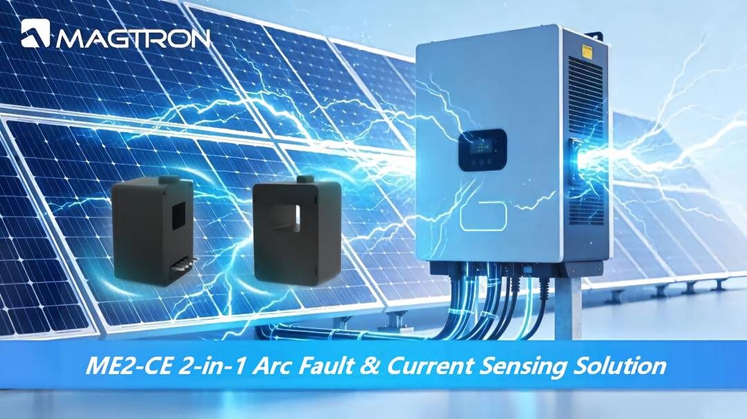
As next-generation power systems continue to scale globally, Battery Energy Storage Systems (BESS) have become essential infrastructure for renewable energy integration, grid frequency regulation, and commercial & industrial backup power applications. Modern BESS platforms are rapidly evolving toward higher power density, higher switching frequency, higher voltage architectures, and global deployment standards.
The stable operation of a BESS heavily depends on the precise coordination between the Battery Management System (BMS) and the Power Conversion System (PCS). As the core sensing element within the system, current sensing is responsible for critical functions including current sampling, power calculation, closed-loop control, and fault protection. Key parameters such as bandwidth, latency, accuracy, and isolation performance directly determine system stability, energy conversion efficiency, and operational safety margins.
This article provides a comprehensive technical analysis of BESS current sensing from four key dimensions: application topology, core technical challenges, mainstream sensing technologies, and engineering-level selection principles.
1. Current Sensing Topology and Core Functions in BESS
A typical BESS consists of battery clusters, BMS, PCS, and power distribution cabinets. Depending on installation location and functional role, current sensing can generally be divided into three categories:
- Battery-side sensing
- Converter-side sensing
- System-level safety sensing
Each category supports different circuit topologies and control strategies.
1. BMS Battery-Side Current Sensing
Installed in series with the main battery cluster circuit, battery-side current sensors are used to measure total charge and discharge current.
These measurements serve as the primary data source for:
- SOC (State of Charge) estimation
- SOH (State of Health) estimation
- Overcurrent protection
- Short-circuit protection
Measurement accuracy directly impacts battery balancing performance and overall battery lifespan, making current sensing one of the foundational elements of BMS control.
2. PCS Converter-Side Current Sensing
Modern PCS platforms typically adopt bidirectional DC/DC + DC/AC topologies. Current sensors are deployed across:
- DC busbars
- Inverter bridge arms
- AC output stages
These sensors provide real-time current feedback for high-frequency switching control of SiC power devices, ensuring stable bidirectional energy conversion through closed-loop regulation while also enabling AC-side power metering and overcurrent protection.
3. System-Level Safety Sensing
System-level safety sensors are typically installed within grounding circuits for:
- Residual current detection
- Insulation fault monitoring
These functions are essential for compliance with energy storage safety regulations and help prevent electrical leakage and insulation failures that could lead to hazardous operating conditions.
2. Core Technical Challenges of BESS Current Sensing
As SiC MOSFET technology becomes increasingly common in PCS applications, switching frequencies have risen from conventional 10kHz levels to 50–200kHz. This significantly increases current ripple frequency while introducing new challenges associated with high-voltage operation, wide environmental conditions, and long system lifecycles.
Current sensing technologies in BESS now face four major technical challenges.
1. High-Frequency Bandwidth and Low-Latency Requirements
Fast current edges generated by high-frequency switching require sensor bandwidths at least three times higher than the system switching frequency. Otherwise, high-frequency components may be attenuated, resulting in waveform distortion.
At the same time, transmission latency must remain within the microsecond range. Excessive delay causes sampling offset, reduces phase margin in the control loop, and may lead to system oscillation.
2. Wide Dynamic Range and High Accuracy
BESS applications must support the full operating range from low-current battery balancing to high-current charging and discharging.
Sensors are therefore required to maintain:
- ≤1%FS accuracy across the full temperature range
- ≤0.5%FS accuracy for high-precision BMS metering applications
In addition, offset drift and temperature drift must be minimized to avoid SOC estimation errors.
3. High Isolation and Strong Noise Immunity
1500V high-voltage ESS architectures require:
- Basic insulation ≥2.5kV
- Reinforced insulation ≥4kV
Sensors must also maintain high common-mode rejection ratio (CMRR) performance in harsh electromagnetic environments to suppress switching noise and surge interference while ensuring signal integrity.
4. International Safety Compliance
For deployment in Europe, North America, and Southeast Asia, current sensing solutions must comply with international standards including:
- IEC 61010-1
- UL 508
- EN 50178
These certifications are essential for meeting local grid and energy storage safety requirements.
3. Mainstream BESS Current Sensing Technologies and Performance Comparison
Current sensing in modern BESS platforms primarily relies on three mainstream technical approaches:
- Shunt resistor + isolated amplifier
- Hall effect sensing
- Fluxgate sensing
Each solution differs significantly in operating principle, performance characteristics, and application suitability.
1. Shunt Resistor + Isolated Amplifier
Operating Principle
Based on Ohm’s Law, current is measured through the voltage drop across a precision resistor and processed through an isolation amplifier.
Characteristics
- High accuracy
- Low temperature drift
- Excellent linearity
- Moderate cost
However:
- Limited bandwidth performance
- Potential common-ground risks
- Less suitable for high-isolation applications
Typical Applications
Best suited for:
- Low-voltage systems
- Cost-sensitive designs
- High-precision metering applications with moderate isolation requirements
2. Open-Loop Hall Current Sensors
Operating Principle
Based on Hall-effect sensing combined with magnetic core concentration, without magnetic compensation structures.
Characteristics
- Low power consumption
- Compact size
- Low cost
- Bandwidth up to 200kHz
- Typical accuracy around 1%FS
However, temperature drift is relatively high.
Typical Applications
Suitable for:
- PCS basic current monitoring
- System overcurrent protection
- Non-precision industrial applications
3. Closed-Loop Hall Current Sensors (Zero-Flux Hall Sensors)
Operating Principle
Utilizes magnetic compensation to maintain zero magnetic flux within the core through a feedback coil.
Characteristics
- Significantly improved linearity and accuracy
- Typical accuracy around 0.8%FS
- Stable bandwidth
- Lower temperature drift
Typical Applications
Widely used in:
- High-frequency PCS closed-loop control
- Commercial & industrial ESS applications
- Precision current feedback systems
This is currently one of the most common sensing solutions in industrial BESS systems.
4. Fluxgate Current Sensors
Operating Principle
Combines excitation detection and magnetic compensation technologies to accurately detect magnetic flux variations using high-frequency excitation signals.
Characteristics
- Ultra-low offset drift
- Fast response speed
- Highest measurement accuracy
- Accuracy ≤0.5%FS
- Response time ≤1μs
- Typical bandwidth: DC–100kHz
Typical Applications
Ideal for:
- High-precision BMS metering
- Utility-scale energy storage systems
- High-accuracy SOC estimation
Fluxgate technology is particularly suitable for applications requiring extremely high stability and precision.
Comparison of Mainstream Current Sensing Technologies
| Technology | Core Principle | Typical Bandwidth | Accuracy | Response Time | Temperature Drift | Typical Application |
|---|---|---|---|---|---|---|
| Shunt + Isolation Amplifier | Ohm’s Law + Resistive Sampling | DC–50kHz | 0.1%–0.5%FS | ≤1μs | Extremely Low | Low-voltage precision metering |
| Open-Loop Hall | Hall Effect without Compensation | DC–200kHz | 1%FS | 2–3μs | Relatively High | Basic monitoring & overcurrent protection |
| Closed-Loop Hall | Hall Effect with Magnetic Compensation | DC–200kHz | 0.8%FS | 1–2μs | Moderate | PCS high-frequency closed-loop control |
| Fluxgate | Excitation Detection + Magnetic Compensation | DC–100kHz | 0.5%FS | ≤1μs | Extremely Low | High-precision BMS SOC estimation |
4. Core Engineering Principles for BESS Current Sensor Selection
1. Bandwidth Matching Principle
Sensor bandwidth should be at least three times the PCS switching frequency to ensure accurate reproduction of high-frequency ripple currents without attenuation or waveform distortion.
2. Latency Control Principle
Total signal transmission delay should satisfy:
t_{delay}<\frac{1}{3f_{sw}}
This prevents sampling offset errors and preserves sufficient phase margin within the control loop.
3. Accuracy and Measurement Range Configuration
Recommended configuration guidelines:
- BMS-side accuracy: ≤0.5%FS
- PCS-side accuracy: ≤1%FS
Sensor current range should reserve:
- 1.5–2× rated current margin
This ensures sufficient headroom for transient overload conditions, while short-circuit protection should be independently validated against maximum system fault current.
4. Environmental and Safety Compliance
Sensors should support:
- Operating temperatures from -40°C to 105°C
- Full-temperature-range operation
For 1500V high-voltage systems:
- Basic insulation ≥2.5kV
- Reinforced insulation ≥4kV
Products should also comply with relevant international safety certifications.
5. Conclusion
Current sensing is one of the most critical functional elements in BESS control and protection systems. Parameters such as bandwidth, latency, accuracy, and isolation capability directly determine overall system efficiency, operational stability, and safety performance.
As SiC-based high-frequency architectures and global ESS deployment continue to expand, the industry increasingly demands current sensing solutions that deliver:
- High-frequency compatibility
- High precision
- Ultra-low latency
- Full international compliance
From high-precision BMS metering to high-frequency PCS closed-loop control, selecting the appropriate sensing technology and matching it correctly to the application scenario is essential for improving energy conversion efficiency, extending battery lifetime, and ensuring long-term system safety.