Introduction
As commercial and industrial energy storage systems continue evolving toward higher power density and more complex grid interaction capabilities, safety is no longer just an optional feature — it has become a fundamental design principle embedded into the DNA of the product itself. A leading energy storage inverter specification sheet not only defines performance boundaries, but also reveals a series of stringent underlying tests related to intrinsic system safety.
Taking today’s mainstream 125kW–150kW three-phase inverters as an example, their grid-side maximum input current capability is typically rated at 250A, with a nominal output current of approximately 190A. This not only demonstrates high power throughput capability, but also imposes a silent yet critical challenge on every internal protection component — especially the leakage current detection module — which must maintain milliamp-level precision under extreme electrical stress conditions.
I. The Safety Principles Behind the Specifications: Deep Interpretation of Standards and Parameter Systems
By analyzing the parameters of mainstream inverters, we can clearly identify a comprehensive safety parameter framework directly associated with various mandatory and recommended international standards.
1. Leakage Current (Residual Current) Requirements and Standards
Core Standards
Standards such as IEC 62109-1/-2 (Safety of Power Converters for Use in Photovoltaic Power Systems), IEC 62477-1 (Safety Requirements for Power Electronic Converter Systems and Equipment), as well as grid connection standards for specific markets (such as Germany’s VDE-AR-N 4105), all impose mandatory requirements on shock protection and insulation fault monitoring in inverter systems.
Parameter Mapping
These standards generally require equipment to provide detection and protection capabilities for both AC and pulsating DC residual currents. In technical specifications, this is typically reflected as a mandatory “leakage current protection” function.
The tripping threshold is not arbitrarily defined. For example, leakage protection intended to prevent electric shock hazards typically adopts a threshold of 30mA. The inverter’s leakage current sensor must reliably detect this minute fault current under both nominal operating current conditions (such as 190A) and maximum transient current conditions (250A), without nuisance tripping or failure to trip.
Key Challenge
The system must simultaneously detect:
- Human safety leakage currents at 30mA
- Fire protection leakage currents corresponding to high-power systems (1500mA for a 150kW system)
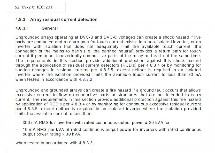
IEC 62109-2 Leakage Current Requirements
2. The Combined Challenge of Current, Voltage, and EMC
Current and Voltage Requirements
The inverter’s AC-side operating voltage range (such as 400V ±15%) and wide current fluctuations require the sensor to deliver exceptionally high dynamic range and linearity.
The sensor must maintain measurement consistency between leakage signals as small as a few milliamps and industrial-frequency load currents as high as 250A.
EMC (Electromagnetic Compatibility) Requirements
The extensive list of safety and EMC standards typically found at the end of inverter datasheets — such as IEC 61000-6-2/-4 — is critically important.
The inverter itself is a powerful source of electromagnetic interference. High-frequency switching generates significant harmonics, conducted noise, and radiated emissions. Leakage current sensors must operate stably in this harsh EMC environment without being affected by internal IGBT switching or external grid surges, requiring extremely high immunity performance in sensor design.
Key Challenge
Ensuring highly accurate small leakage current detection under large system currents approaching 250A.
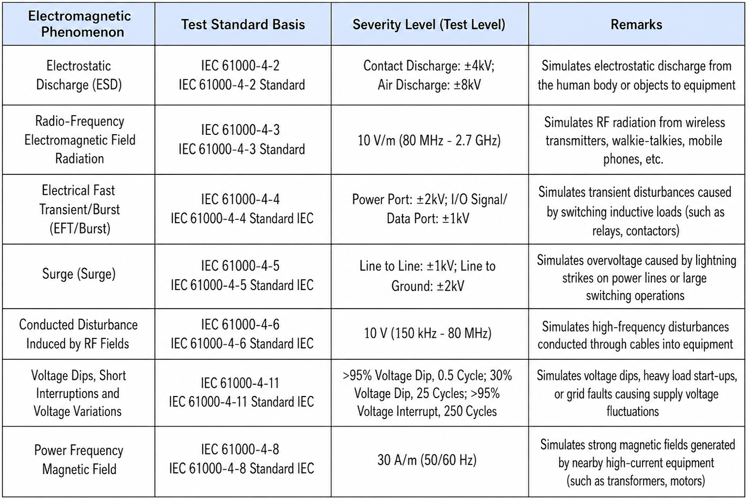
EMC Test Requirements
II. Monitoring Difficulties on the 250A Side: The Physical Nature and Testing Limits of Unbalanced Magnetic Field Interference
Achieving milliamp-level leakage current accuracy under 250A operating conditions involves far more than simply “detecting small signals in large currents.”
One of the most critical yet often overlooked challenges originates from the physical structure of the sensor itself — namely, the “unintentional unbalanced magnetic field interference” caused by unavoidable conductor spacing differences in three-phase four-wire measurement systems.
1. Mechanism of Unbalanced Magnetic Field Generation
Traditional leakage current monitoring solutions are now encountering fundamental physical limitations when facing the 250A+ operating currents commonly found in modern 125kW to several hundred-kilowatt energy storage converters.
The core difficulty is not merely measuring tiny signals in the presence of large currents, but rather a systemic interference issue caused by unavoidable physical asymmetry in three-phase four-wire conductor layouts.
In an ideal model, the vector sum of currents in a three-phase four-wire system is zero, meaning the resulting magnetic field should also theoretically cancel out completely.
However, in real electrical cabinet layouts, PCB routing, or busbar installations, the L1, L2, L3, and N conductors cannot achieve perfectly symmetrical geometry or equal spacing. Even millimeter-level spacing deviations can generate residual magnetic fields under 250A industrial-frequency currents according to the Biot-Savart Law.
This interference field, caused by “unintentional geometric imperfections,” is interpreted by the sensor as a significant background noise signal or “false leakage current.”
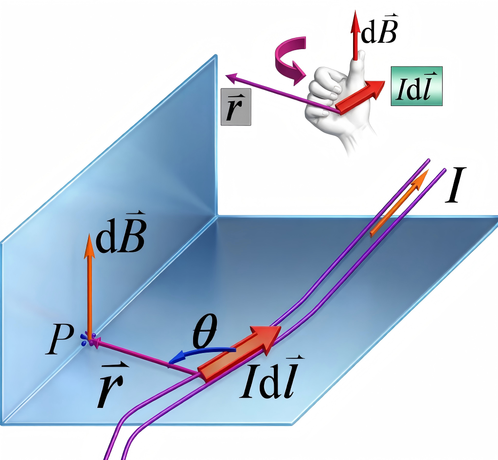

Biot-Savart Law
The interference intensity increases proportionally with load current. Under full-load operation, this noise can easily exceed tens or even hundreds of milliamps, completely masking real fault signals — including the critical 30mA human safety protection threshold.
As a result, the protection system may fail during critical moments or suffer from frequent nuisance tripping, severely compromising system reliability. This has effectively become the “Achilles’ heel” of leakage current protection in modern high-power energy storage systems.
III. The Paradigm Shift: From Open-Loop Measurement to Closed-Loop Sensing and Active Protection
To fundamentally address this physical-layer challenge, innovation at the sensing principle level is essential.
The newly developed three-phase four-wire leakage current sensor abandons the conventional approach of incremental improvements based on traditional open-loop Hall-effect or fluxgate technologies. Instead, it achieves a true paradigm shift through two major technological breakthroughs.
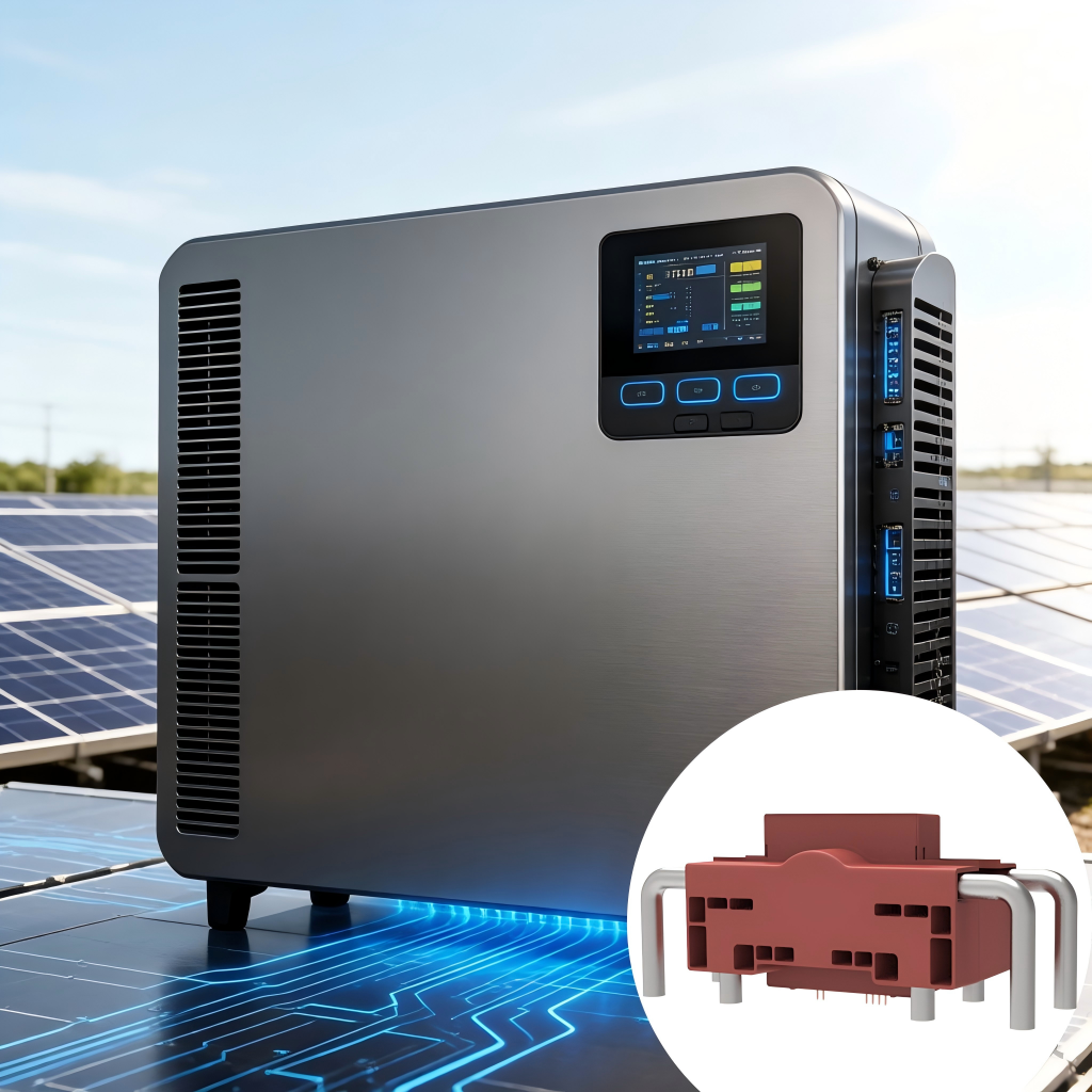
1. First Breakthrough: “Zero-Flux” Locking Technology Based on an Innovative Closed-Loop Fluxgate Principle
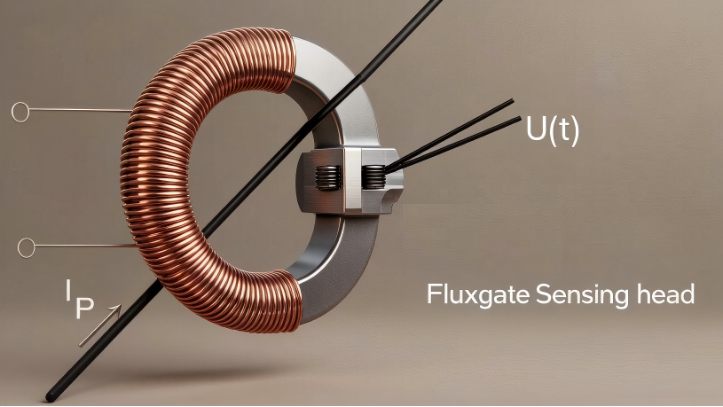
The core innovation lies in adopting an advanced closed-loop fluxgate detection principle.
Unlike open-loop solutions that passively measure magnetic fields, the closed-loop system actively injects compensation current into the compensation coil through a high-precision feedback loop, dynamically maintaining absolute zero net magnetic flux inside the sensor core.
Its operating principle can be summarized as:
“Detection Through Cancellation”
When a real fault leakage current appears on the primary conductor, the feedback system immediately injects an equal and opposite compensation current to maintain the zero-flux state.
This compensation current value becomes the accurately linearized leakage current measurement result, completely independent of the magnitude of the main operating current.
This means that whether the external working current is 1A or 250A — or whether interference magnetic fields are generated by uneven conductor spacing — the operating point of the system is always forcibly locked within the zero-flux region, where sensitivity and linearity are optimal.
Fundamentally, this frees the sensor from the challenge of enduring massive common-mode magnetic fields, allowing it to respond only to unbalanced differential signals (i.e., leakage currents), theoretically achieving unlimited common-mode rejection capability.
2. Second Breakthrough: Multi-Layer Active Electromagnetic Shielding Architecture
A precise sensing principle alone is not sufficient.
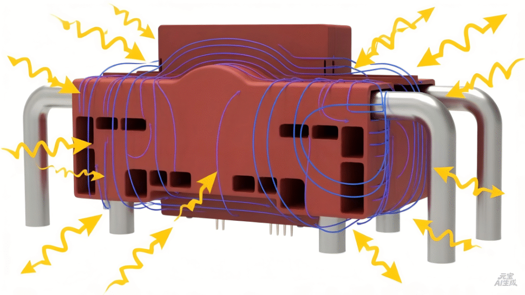
To withstand the extremely harsh electromagnetic environment inside modern converters — including high-frequency di/dt and dv/dt switching noise, as well as spatial stray magnetic fields — we have established multiple active shielding mechanisms at both mechanical and circuit levels.
High-Permeability Alloy Shielding Layer
Externally, the sensor incorporates a customized multi-layer high-permeability alloy shielding enclosure.
Like a “magnetic Faraday cage,” it effectively bypasses and attenuates low- to mid-frequency stray magnetic fields, creating a magnetically quiet zone for the precision magnetic core.
Equipotential Shielding and Optimized PCB Layout
Within the internal PCB and sensitive signal paths, equipotential shielding technology and carefully optimized grounding strategies are employed to eliminate capacitive coupling paths and significantly reduce common-mode interference caused by voltage transients.
These two technologies are not simply stacked together — they are deeply integrated.
The closed-loop fluxgate principle fundamentally solves internally generated interference caused by geometric asymmetry and high currents, while the multi-layer shielding architecture protects against externally generated EMI disturbances.
Together, they ensure the ultimate reliability of the sensor under real-world operating conditions.
As the energy storage industry continues pursuing higher efficiency and greater power density, safety remains the one foundation that can never be compromised.
The precision and reliability of leakage current monitoring are essential components of that foundation.
We firmly believe that by innovating at the physical-principle level — leveraging closed-loop fluxgate technology and system-level electromagnetic shielding to overcome monitoring challenges under high common-mode currents — we are not only delivering a high-performance sensor to the market, but also providing the industry with a more robust and trustworthy safety technology solution.
We look forward to collaborating with leading energy storage system manufacturers to integrate this precision and reliability, born from fundamental innovation, into every high-performance energy storage converter, jointly driving the industry forward with both safety and performance advancing in parallel.