1. Mechanism of Inverter Grid-Connection Inrush
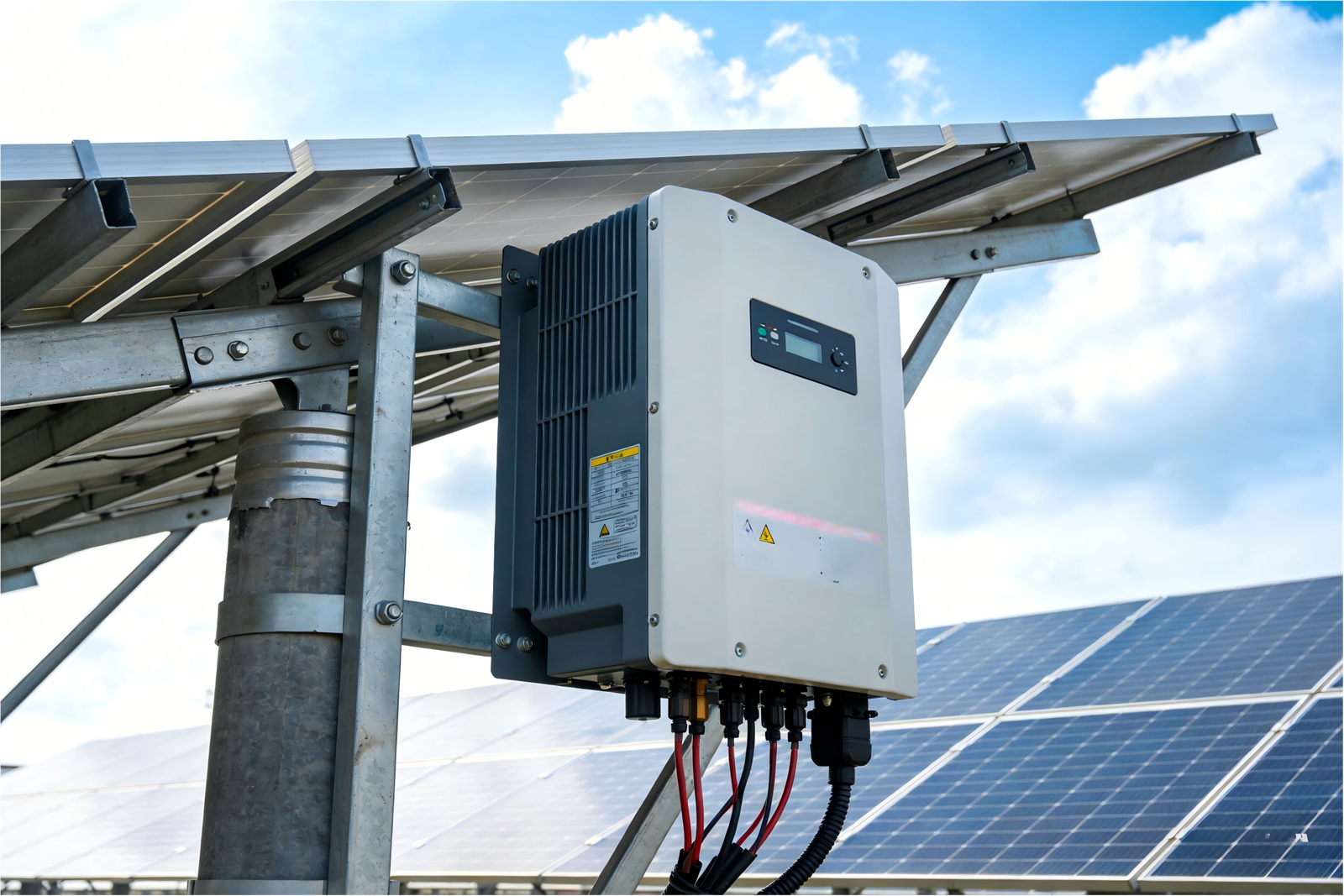
At the instant when a photovoltaic power generation system is connected to the grid, grid-connected inverters often generate a short-duration inrush current. This phenomenon is directly related to the stability of electrical equipment and the power quality of the grid, and it significantly affects the reliability of inverter products.
The core mechanism of grid-connection inrush originates from the instantaneous deviation between the inverter output voltage and the grid voltage in terms of amplitude, phase, or frequency during the synchronization process, as well as the rapid charging and discharging characteristics of the DC-side filter capacitor. In addition, the high-frequency switching behavior of power electronic devices, coupled with grid impedance, further intensifies the transient pulse characteristics of the current.
The insufficient surge withstand capability of existing components has become a key bottleneck limiting system reliability. Statistics show that approximately 32% of inverter failures are caused by component-level damage due to grid-connection inrush. In this context, breakthroughs in the surge immunity performance of RCMU devices provide a more robust solution for the industry.
2. Inrush Fault Phenomena and Model Analysis
2.1 Description of Actual Grid-Connection Inrush Phenomena
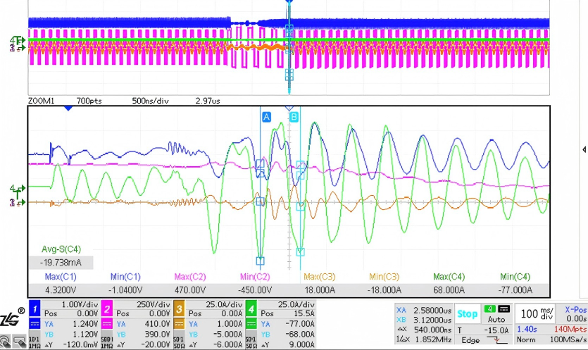
(Actual inrush current waveform)
In this waveform, Channel 4 (CH4) represents the grid-connection inrush current, which appears as a damped resonant current. The peak current reaches 77 A, with a resonant frequency of 1.852 MHz. At the initial moment of oscillation, the current exhibits an extremely high di/dt.
According to Faraday’s law of electromagnetic induction, such rapid changes in the electric field generate strong magnetic fields in conductors, which in turn induce voltages that may damage internal components.

Where:
– i₁ is the inrush current
– V₂ is the induced voltage in the device
– M is the equivalent mutual inductance between the grid connection path and the internal circuit
Devices containing magnetic components and located close to the grid connection path tend to have higher mutual inductance and are therefore more susceptible to damage under inrush conditions, such as RCMUs and relays. Field feedback indicates that such inrush events frequently lead to failures of output-side relays and RCMU devices.
2.2 Equivalent Circuit Modeling of Grid-Connection Transients
Consider the circuit conditions of the inverter output and the grid at the moment of connection. Due to the limited response speed of the control system, the inverter output voltage cannot instantly synchronize with the grid, resulting in a phase difference. This is equivalent to applying a step excitation to the circuit.
The inverter output filter and parasitic inductances in the circuit form an LC series structure, which produces resonant current under this excitation. The equivalent circuit at the moment of grid connection consists of an inductor (L), a capacitor (C), and an equivalent step voltage source.

( Circuit diagram and equivalent model)
When a voltage source generates a step signal of magnitude V at time 0, the impulse current is

This formula represents a sinusoidal resonant signal with gradually decaying amplitude, where the resonant frequency is

The peak value of the resonant circuit is

The derived expression from this equivalent model matches the measured waveform. Evaluating the worst-case scenario, the inrush current is maximized when the step voltage amplitude is highest, corresponding to complete phase mismatch between the inverter and the grid, approximately 440 V.
The resonant frequency is determined by the equivalent LC parameters, and a larger C/L ratio results in a higher peak current.
Therefore, applying a step excitation to a given LC series circuit can effectively simulate the inrush current during inverter grid connection.
3. Inrush Fault Simulation and Surge Withstand Testing
3.1 Circuit Simulation and Evaluation
A circuit model was first built in LTspice to simulate the inrush current.
In this model:
– Switch S1 is located on the voltage source (V1) side
– Switch S2 is located between the LC components
The circuit operates in two modes:
1. S1 is turned on and S2 is off, allowing V1 to charge capacitor C1 to 400 V
2. S2 is turned on while S1 is turned off, causing C1 to discharge into the RLC circuit
To achieve a sufficiently high resonant frequency, the value of C1 must be small. However, this leads to rapid voltage drop due to internal equivalent parallel discharge paths. Therefore, S1 and S2 must use power semiconductor devices with switching speeds at least an order of magnitude faster than the discharge time, so that capacitor leakage effects can be neglected.
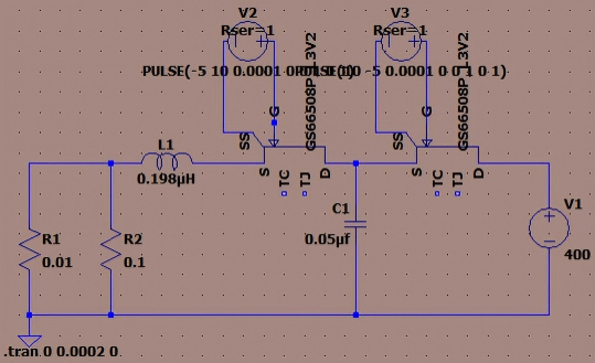
( Simulation circuit)
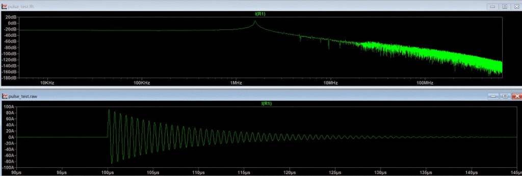
(Simulation waveform)
The simulated resonant current peak is 92 A, with a resonant frequency of 1.607 MHz, indicating that the circuit parameters meet the design requirements.
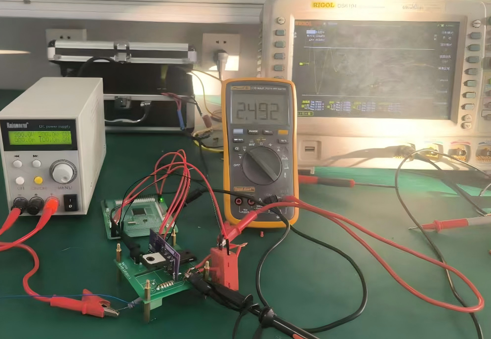
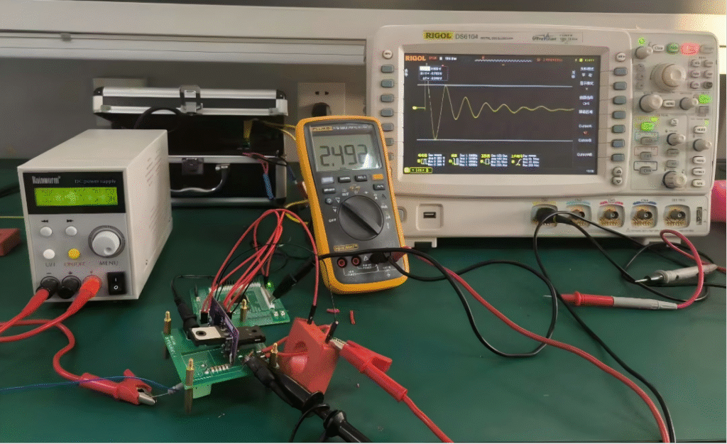
3.2 Experimental Validation with Physical Circuit
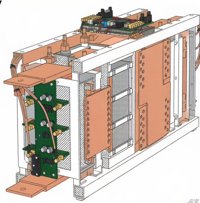
To closely replicate the inverter grid-connection inrush and verify the robustness of Magtron’s RCMU products, a physical test circuit was constructed. RCMU devices were connected in series within the test loop.
The peak inrush current was controlled by adjusting the output voltage of the high-voltage power supply.
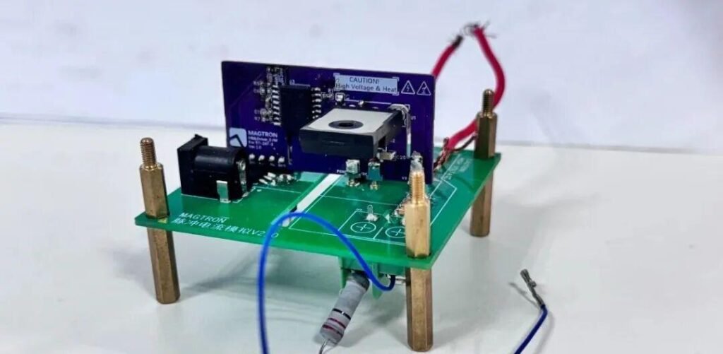
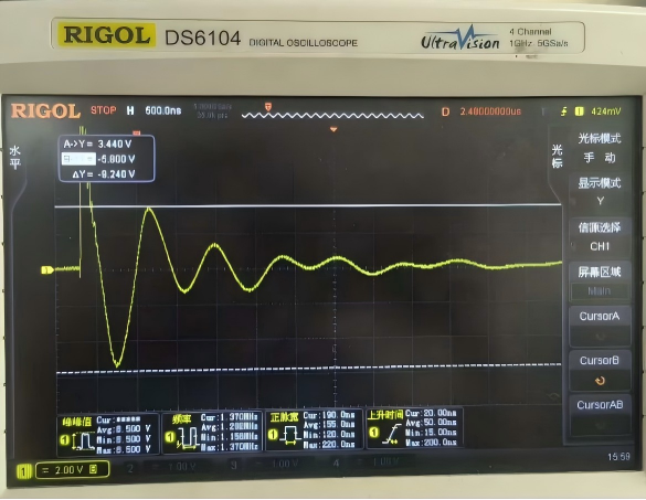
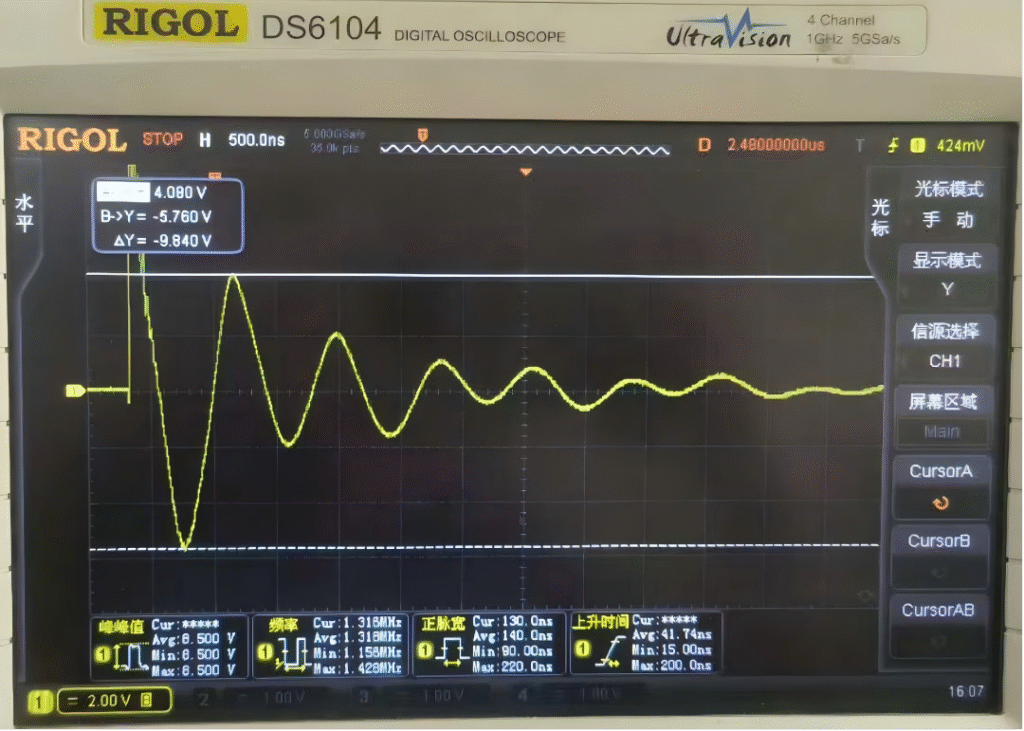
(Inrush simulation test circuit)
During testing, the maximum power supply voltage was set to 500 V (limited by the 600 V rating of the switching devices). The simulated peak inrush current reached 98.4 A, with a resonant frequency of 1.33 MHz, closely matching real grid-connection conditions.
Two RCMU models were tested with three samples each. Under these conditions, neither model exhibited failure, demonstrating excellent surge immunity and suitability for inverter applications.
( RCMU product series)
4. Technical Recommendations for Mitigating Grid-Connection Inrush
1. Select components with superior surge withstand capability
Test results show that Magtron RCMU series products maintain reliable and accurate operation under grid-connection inrush conditions. They can withstand surge currents exceeding 50 kA under the 8/20 μs surge test standard, meeting the requirements of harsh real-world inverter applications.
2. Implement pre-synchronization techniques
The root cause of inrush is the phase difference between the inverter and the grid at the moment of connection. Deploying voltage sensors on the grid side and performing phase synchronization prior to connection can effectively eliminate this issue.
3. Optimize output filter parameters
The equivalent circuit model shows that inrush current depends on LC parameters, which are primarily determined by the output filter. Adjusting LC values can help control the peak amplitude and oscillation frequency of the inrush current, thereby reducing its impact.