Introduction
The global photovoltaic (PV) industry is undergoing a fundamental shift—from a focus on efficiency alone to system-level performance optimization.
With the rapid adoption of silicon carbide (SiC) power devices in PV inverters—expected to exceed 35% market penetration by 2025 (Yole forecast)—current sensing technologies are facing unprecedented demands.
As one of the few companies with fully in-house developed Hall-effect sensor ICs, we are introducing a 2 MHz bandwidth current sensing chip that redefines monitoring capabilities in high-frequency power electronics systems.
1. SiC Devices Reshaping PV Inverter Architecture
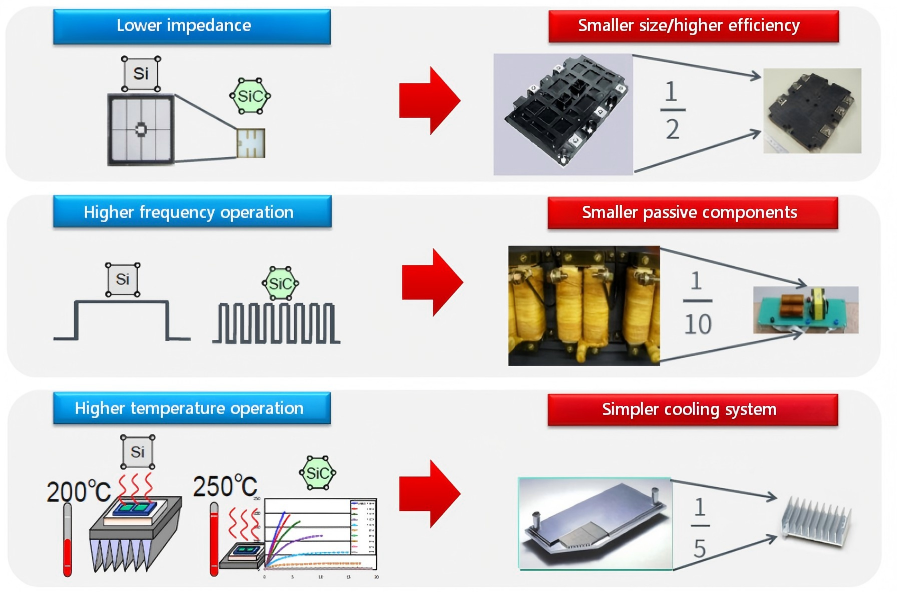
Technology Breakthroughs
- 3–5× higher switching frequency
State-of-the-art SiC modules now operate above 100 kHz, compared to ~20 kHz for traditional IGBTs, reducing passive component size by up to 60% - System efficiency exceeding 99%
In 1500 V PV inverter systems, SiC-based designs achieve >99% efficiency, while IGBTs struggle to meet the 25-year lifetime requirements of PV + energy storage systems due to higher losses - Superior thermal performance
Third-generation SiC devices (e.g., Wolfspeed) can operate reliably at 200°C, enabling more compact thermal designs - Cost inflection point approaching
With mass production of advanced 8-inch wafers, the cost gap between SiC and silicon has narrowed to ~1.3× in 2024 (down from 4× in 2020), delivering lifecycle cost advantages in systems above 150 kW
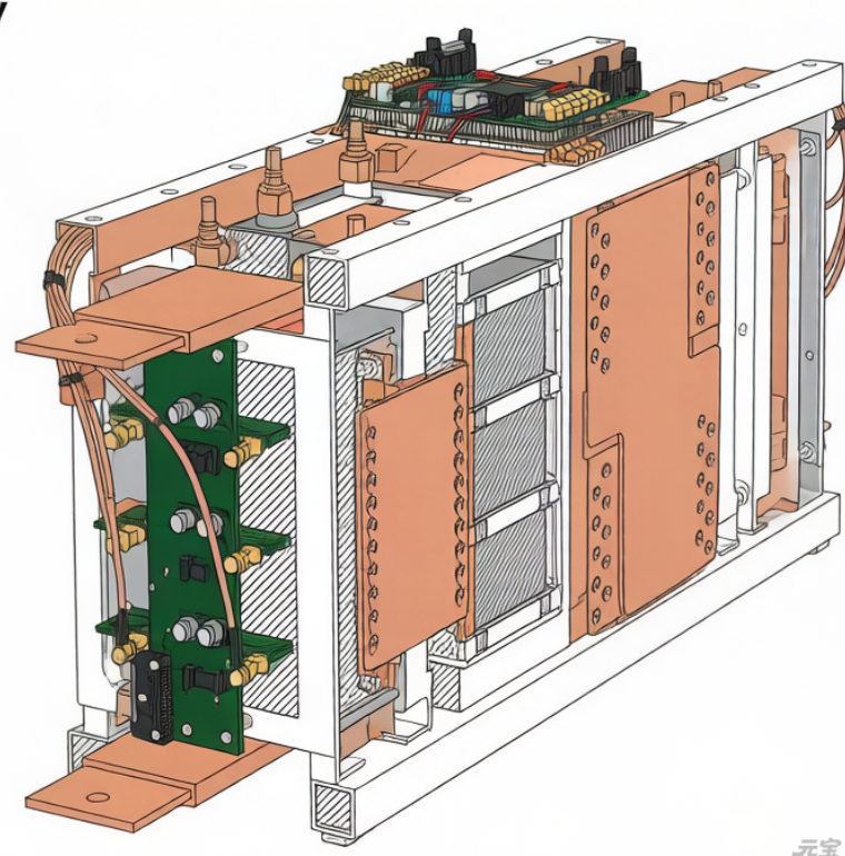
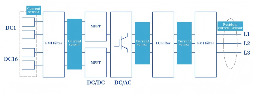
2. Key Current Sensing Nodes in PV Inverters
High-frequency current sensors play a critical role across multiple stages:
(1) PV String Input (DC Side)
Location: Between PV strings and inverter DC input
Function:
- Enable Maximum Power Point Tracking (MPPT)
- Detect overcurrent and short circuits
- Protect DC bus capacitors and power devices
(2) DC/DC Boost Stage Output
Location: Boost inductor or DC/DC converter output (DC bus)
Function:
- Monitor DC bus current
- Stabilize voltage
- Support fast dynamic response with high-frequency SiC switching
(3) Inverter Bridge AC Output (AC Side)
Location: Output of H-bridge or three-phase bridge (before filter inductor)
Function:
- Real-time AC waveform acquisition
- Enable PWM modulation and closed-loop control
- Detect overload and harmonic distortion (THD < 3%)
(4) Grid Connection Point
Location: After output filter, at grid interface
Function:
- Monitor grid current
- Ensure compliance with grid codes (e.g., LVRT)
- Detect islanding conditions
(5) Industry Validation
Utility-Scale PV Project (200 MW, Ningxia)
- SiC-based three-level topology
- Switching frequency increased to 75 kHz
- High-frequency sensors improved MPPT dynamic response by 40%
- Daily energy yield increased by 2.7%
- Passed 1500 V full-load operation test for 72 hours (CQC certification)
Tesla Powerwall 3 Evolution
- Switching frequency increased to 120 kHz
- Requires overcurrent protection within 5 µs
- Imposes strict sensor response time requirement: < 1 µs
3. Challenges in High-Frequency Current Sensing
Industry Pain Points
- Transient blind spots
At switching frequencies above 100 kHz, conventional sensors (<200 kHz bandwidth) miss over 30% of critical transient events - Severe electromagnetic interference (EMI)
High-frequency operation increases common-mode noise by ~20 dB, requiring CMTI ≥ 120 kV/µs - Thermal and space constraints
Modular designs reduce available sensor space to one-quarter of traditional layouts
4. Magtron Solution
2 MHz Bandwidth – Full Transient Visibility
- Captures ringing, overshoot, and fast switching dynamics
- Time resolution up to 200 ns
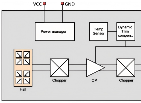
A 10 MHz modulation/demodulation architecture enables breakthroughs in both time and frequency domains:
- High-frequency chopping in the signal path
- High-bandwidth operational amplifiers
- Advanced digital filtering
Together, these deliver significantly enhanced system-level bandwidth and signal fidelity.
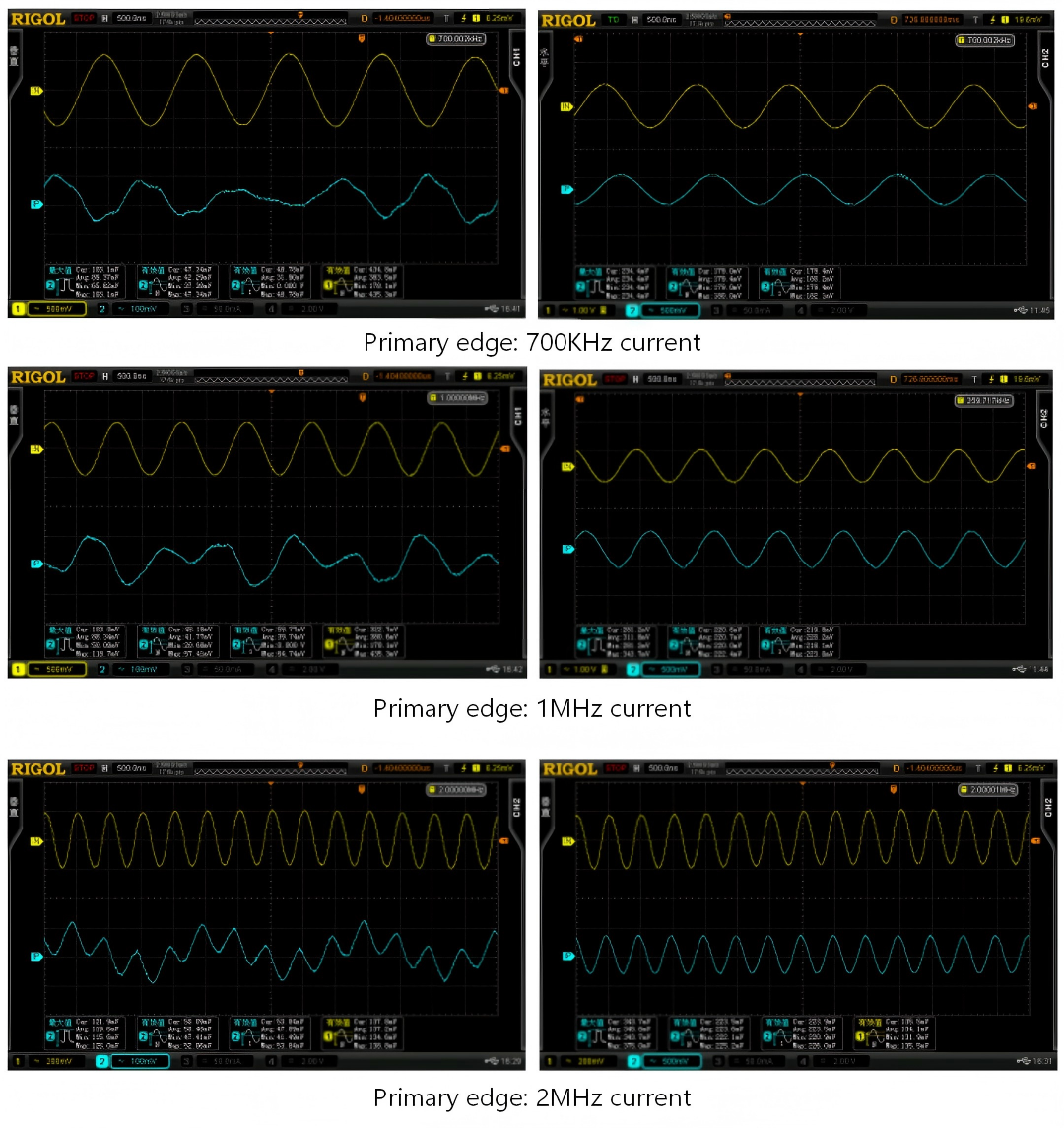
Performance Comparison
- Conventional 200 kHz sensors(Left): Limited transient visibility
- Magtron 2 MHz sensor(Right): Full high-frequency waveform capture
Key Technology Features
- Integrated magnetic flux focusing structure
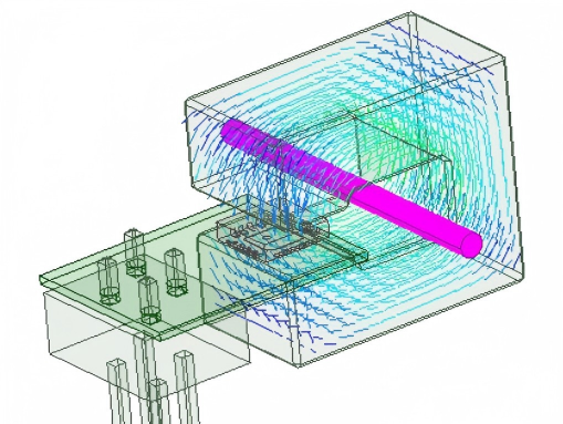
- Multi-core sensing architecture
- Improves accuracy and bandwidth
- Enhances EMI immunity
- Wide temperature operation: −40°C to +125°C
- Accuracy maintained within ±0.5% FS
- Built-in temperature sensing for real-time compensation
- Adaptive overcurrent protection
- Provides fault signaling to downstream systems
5. Conclusion
As PV inverter power density approaches 50 kW/L and SiC switching losses drop to one-fifth of silicon-based solutions, current sensing is evolving from a supporting component to a system enabler.
We invite industry partners to explore the limits of high-frequency power electronics sensing—leveraging million-samples-per-second data insight to ensure every watt of clean energy is converted with maximum precision and reliability.