Introduction
As the global energy transition converges with the rapid expansion of the digital economy, power systems are accelerating toward greater efficiency, intelligence, and flexibility. As the core component of power transmission and conversion, transformers are becoming a critical focal point for technological innovation and high-quality industry development.
Conventional transformers, built on the principle of electromagnetic induction, have long supported the operation of modern power grids. However, with the rise of renewable energy integration, explosive AI computing demand, and smart grid deployment, their limitations—including bulky size, rigid architecture, and limited functionality—are becoming increasingly evident.
Driven by next-generation power semiconductor technologies, Solid-State Transformers (SSTs) are emerging as a disruptive upgrade and a key interface connecting modern power systems with diversified end-use applications. According to reports from authoritative research institutions including GGII, the global SST market was valued at approximately USD 1.5 billion in 2025 and is projected to reach USD 12 billion by 2030, representing a compound annual growth rate (CAGR) of over 35% from 2025 to 2030. China is expected to lead global market growth, with its SST market reaching approximately RMB 4.2 billion in 2025, up 38.2% year-over-year. CCID Consulting further forecasts that China’s SST market will maintain a CAGR exceeding 40% between 2025 and 2030, surpassing RMB 35 billion by 2030 and becoming the world’s largest single SST market.
Enabled by advanced power semiconductor technologies, SSTs are redefining power conversion architectures and becoming essential equipment for future energy infrastructure and intelligent electrical loads. With deep expertise in magnetic sensing and control IC technologies, Giant Magnet Intelligent remains closely aligned with the forefront of the power industry. This article analyzes the current status and future trends of the SST industry from four dimensions—technology comparison, industrial chain, application scenarios, and domestic enterprise landscape—while highlighting the core value of Giant Magnet Intelligent in this evolving ecosystem.
I. The Final 100 Meters: The Evolutionary Battle Between Conventional and Solid-State Transformers
In the “last 100 meters” of the power network—from distribution rooms to server racks, from energy storage containers to EV charging stations—traditional transformers are facing unprecedented challenges. Their bulky structure and inflexible architecture not only consume increasingly valuable urban space, but also struggle to handle the rapidly fluctuating loads driven by AI computing infrastructure. Today, the rapid rise of Solid-State Transformers is reshaping this landscape.
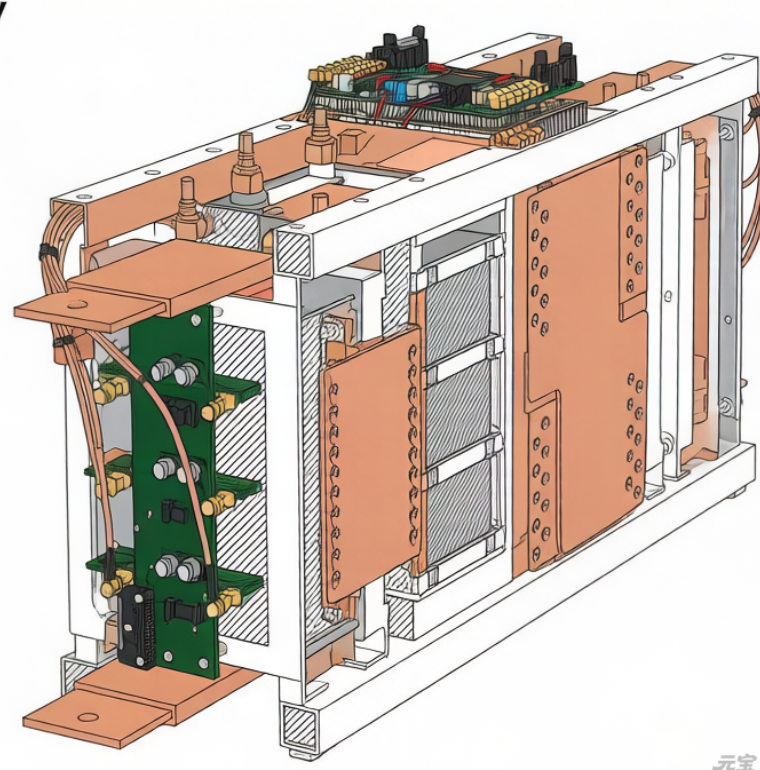
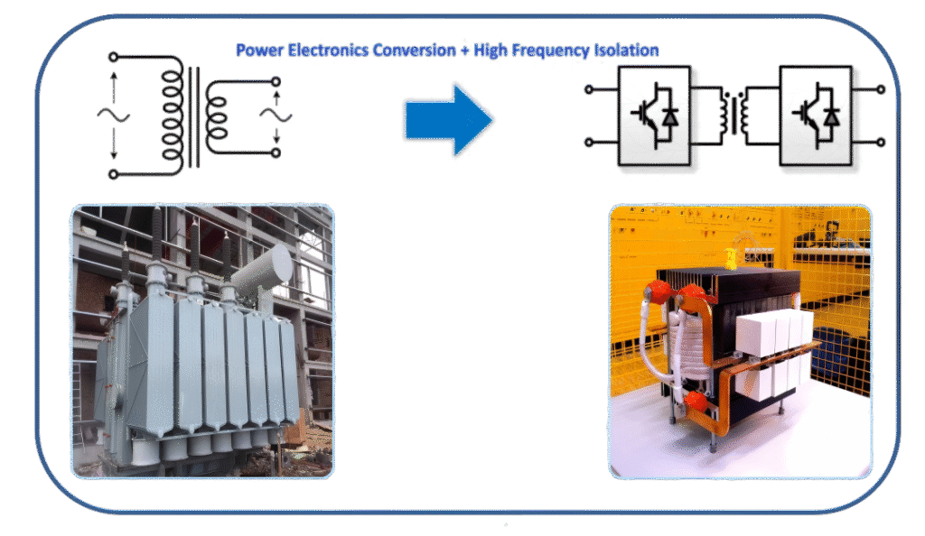
A Solid-State Transformer, also known as a Power Electronic Transformer (PET), is a next-generation power conversion device built on advanced power electronics, high-frequency conversion technologies, and intelligent control systems. Its core functions include voltage conversion, bidirectional power flow, and power quality management. Compared with conventional transformers, SSTs fundamentally represent a technological shift from “electromagnetic induction” to “power electronics-based conversion.”
To fully understand the value of SST technology, it is essential to first clarify the core technical differences between SSTs and conventional transformers, while objectively evaluating the strengths and limitations of each. This helps define the practical application boundaries and long-term development potential of SSTs.
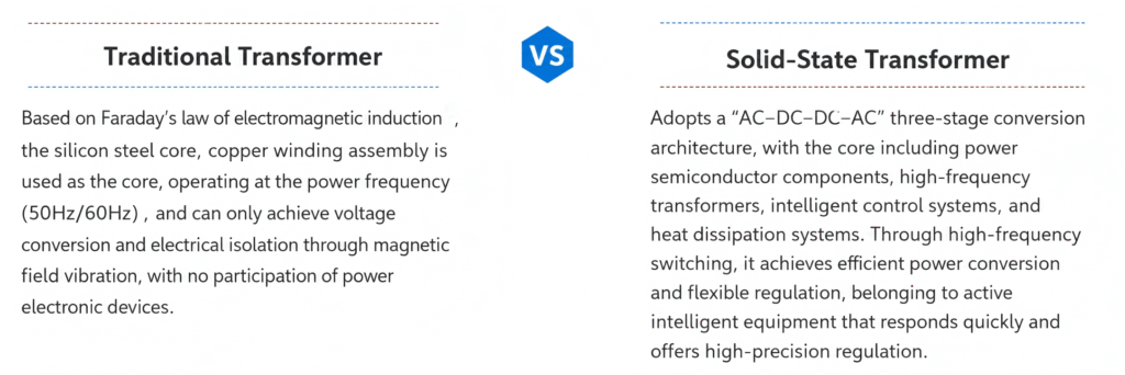
1.1 Differences in Core Technical Principles
1.2 Comprehensive Comparison Across Key Dimensions
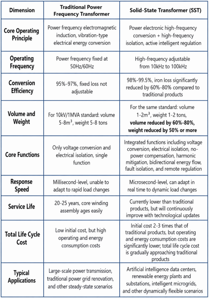
From the four critical dimensions of performance, size, functionality, and maintenance, the differences between conventional transformers and SSTs become clear, highlighting the core advantages of SST technology:
1.3 Summary of Advantages, Limitations, and Application Boundaries
Core Advantages of SSTs
- Higher energy efficiency and lower power losses
- Compact size and lighter weight
- Integrated multifunctional capabilities
- Simplified operation and maintenance
- Fast dynamic response
These advantages align closely with global carbon reduction goals and the requirements of next-generation power systems.
Current Limitations of SSTs
- Higher initial investment cost
- Significant technical complexity
- Greater thermal management challenges
- Incomplete industry standards and certification systems
Rather than being direct replacements, conventional transformers and SSTs will coexist for the foreseeable future. Conventional transformers still maintain cost advantages in large-scale bulk power transmission applications, while SSTs are becoming irreplaceable in emerging high-performance scenarios and are expected to gradually move toward mainstream adoption.
II. SST Core System Design and Topology Architecture Analysis
This section focuses on the system-level design of Solid-State Transformers (SSTs), including mainstream topology architectures and optimization strategies for critical functional stages, providing a comprehensive overview of the technical foundation behind SST technology.
2.1 Mainstream SST Topology Architectures and Hierarchical Design
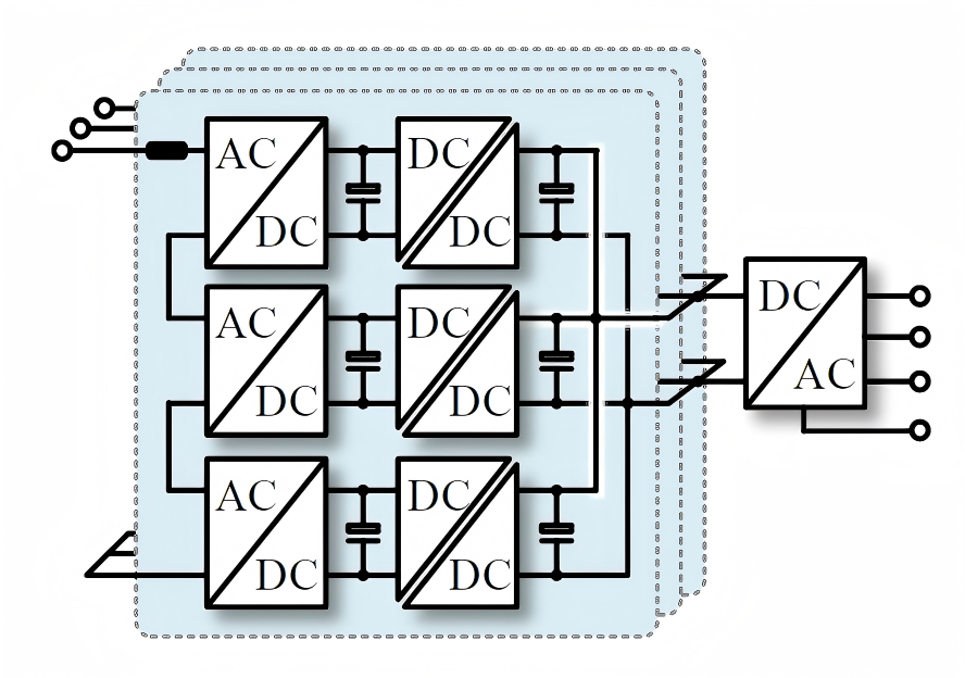
Depending on application voltage and power levels, SST topologies are generally divided into single-phase and three-phase architectures. Among them, three-phase topologies are primarily used in medium- and high-voltage, high-power applications such as power grids, renewable energy systems, and data centers, making them the current focus of industry R&D and commercialization.
Input-Stage Topology Design
In medium- and high-voltage applications, the input stage mainly adopts either Cascaded H-Bridge (CHB) or Modular Multilevel Converter (MMC) topologies.
Cascaded H-Bridge (CHB) Topology
The CHB topology features a relatively simple structure, high modularity, and lower control complexity. It is currently the mainstream solution in commercially deployed SST products in China. It is well suited for 10 kV distribution network applications and allows flexible adaptation to different voltage levels through modular cascading.
Modular Multilevel Converter (MMC) Topology
The MMC topology provides superior output waveform quality and lower harmonic distortion, making it highly suitable for 35 kV and higher-voltage applications. It offers significant advantages in ultra-high-voltage flexible DC transmission systems and large-scale renewable energy integration. However, it also requires more sophisticated control algorithms.
Isolation-Stage Topology Design
The isolation stage is the core of SST technology for achieving high-frequency isolation and efficient energy transfer, and it is also the primary focus of topology optimization.
The industry mainly adopts the Dual Active Bridge (DAB) topology and its optimized resonant derivatives, including:
- Series Resonant Converter (SRC)
- LLC Resonant Converter
These topologies can be flexibly selected according to specific operating conditions and system requirements.
Output-Stage Topology Design
The output stage can generally be categorized into two types based on load requirements:
Three-Phase Full-Bridge Inverter Topology for AC Loads
This topology delivers stable utility-frequency AC output while also supporting reactive power compensation and harmonic mitigation.
DC/DC Buck-Boost Topology for DC Loads
This topology provides stable DC voltage output and is widely used in:
- Data centers
- DC fast charging stations
- Energy storage systems
It is currently one of the fastest-growing SST application segments.
2.2 Optimization of Core Isolation-Stage Topologies: DAB vs. SRC
The choice of isolation-stage topology directly determines SST system efficiency, power density, and operational stability. Currently, the two most representative solutions are the DAB topology and the SRC topology.
Dual Active Bridge (DAB) Topology
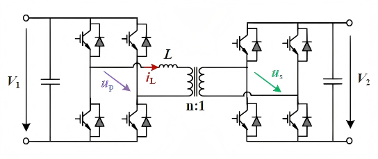
The DAB topology is the classical solution for SST isolation stages. It consists of full-bridge circuits on both sides of a high-frequency transformer, enabling bidirectional power transfer.
Key advantages include:
- Simple control logic
- Fast dynamic response
- Excellent suitability for bidirectional energy flow applications
Its core feature is Zero Voltage Switching (ZVS) during turn-on operations for all switching devices. However, because switches turn off at peak current conditions, tail currents generate relatively high turn-off losses, particularly under light-load conditions where efficiency drops become more noticeable.
Series Resonant Converter (SRC) Topology
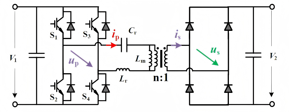
The SRC topology introduces a resonant tank based on the DAB architecture, enabling both:
- Zero Voltage Switching (ZVS)
- Zero Current Switching (ZCS)
This fundamentally eliminates turn-off losses in switching devices. Compared with DAB, overall system efficiency can improve by approximately 0.5%–1%, delivering superior efficiency under rated operating conditions.
However, the resonant behavior also increases peak current levels, which raises conduction losses. As a result, SRC topologies are generally less adaptable than DAB under wide load fluctuation conditions.
Comparative Summary
Overall:
- DAB topologies are better suited for renewable energy and energy storage applications involving bidirectional power flow and significant load variation.
- SRC topologies are more suitable for data centers and ultra-fast charging stations, where operating conditions are relatively stable and extremely high efficiency is required.
The industry is also beginning to adopt hybrid topology approaches that combine the advantages of both architectures to further optimize SST efficiency across wider operating ranges.
2.3 SST Structure and Fundamental Control Architecture
2.3.1 A Generalized SST Architecture
F. Wald et al., “Applications and Services of Solid-State Transformers in Active Distribution Networks—A Critical Review,” IEEE Transactions on Smart Grid, vol. 16, no. 5, pp. 3615–3637, Sept. 2025, doi: 10.1109/TSG.2025.3574007.
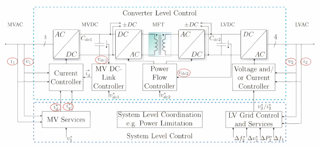
At present, the academic community has not yet reached a consensus regarding the optimal circuit configuration for grid-connected SST applications. Therefore, to better illustrate SST characteristics, the figure above presents a generalized and functionally comprehensive topology consisting of a three-stage power electronic converter architecture capable of interconnecting medium-voltage (MV) and low-voltage (LV) AC/DC networks.
The control architecture of a three-stage SST can be divided into three independent fundamental controllers:
- Medium-voltage converter controller
- DC/DC converter controller
- Low-voltage converter controller
The overall control framework consists of two layers:
- Fundamental controller layer (green blocks)
- Service-oriented controller layer (blue blocks)
Signals marked with an asterisk (*) represent reference values rather than measured values. Signals highlighted in red indicate key measurement nodes requiring dedicated sensing components.
1) Medium-Voltage Converter Control
As shown in the upper-left section of the diagram, the medium-voltage-side converter is an AC/DC converter whose control strategy resembles that of a conventional active front-end converter.
Its core function is to regulate the AC-side current (i_1) through cascaded current-voltage controllers while stabilizing the medium-voltage DC bus voltage (v_{dc1}) at the reference value (v^*_{dc1}).
A feedforward control structure can also be implemented by introducing the measured grid voltage (v_1) after the current controller.
The medium-voltage converter can adopt various topologies, with the Modular Multilevel Converter (MMC) being the most widely used. MMC topologies require sophisticated modulation strategies along with additional voltage-balancing and common-mode compensation controllers to ensure stable operation.
Additional service-oriented control loops can also be cascaded onto the basic control framework to generate new dq-axis current reference values.
For example:
- Harmonic compensation can be achieved by superimposing oscillating active current components onto the active current reference (i^*_d).
- Voltage/reactive power support services require voltage magnitude reference inputs such as (v^*_1).
More advanced grid-support functions can also be implemented, enabling Grid-Forming (GFM) control capability on both sides of the converter.
By introducing DC bus voltage droop control characteristics in the DC-side converter, responsibility for maintaining DC bus voltage can be distributed across interconnected grids. The energy support required for GFM operation can be coordinated through downstream low-voltage networks.
Using information such as frequency deviation and voltage deviation, SSTs can further exploit load-side active power flexibility to achieve internal power flow regulation.
2) DC/DC Converter Control
The upper-middle DC/DC conversion stage shown in the diagram is primarily responsible for:
- Maintaining low-voltage DC bus stability
- Transferring power from the MV DC bus to the LV DC bus
Using the Dual Active Bridge (DAB) topology as an example, bidirectional power transfer is achieved by controlling the phase shift between the primary and secondary voltages of the medium-frequency transformer (MFT), thereby controlling current direction and magnitude.
The core control objective of this stage is implemented through the power flow controller module shown in the center of the diagram, whose inputs include:
- Measured low-voltage DC bus voltage
- Reference voltage (v^*_{dc2})
Lower-level control and modulation techniques can be flexibly selected according to topology and operating conditions, including:
- Linearized control
- Disturbance observer-based control
- Sliding mode control
Advanced soft-switching algorithms such as Zero Voltage Switching (ZVS) in DAB converters can significantly:
- Improve conversion efficiency
- Extend device lifespan
- Reduce thermal stress on power switches
Today, advanced soft-switching techniques are increasingly being adopted in current-source inverters and specialized complex converter topologies to further improve efficiency.
3) Low-Voltage Converter Control
The low-voltage-side DC/AC converter shown in the upper-right section of the diagram adopts different control strategies depending on application requirements.
At the fundamental control level, the converter can operate in either:
- Grid-Forming (GFM) mode
- Grid-Following (GFL) mode
According to industry-standard definitions, a Grid-Forming controller must maintain its internal voltage phasor constant—or nearly constant—within sub-transient and transient time scales.
This can be achieved through:
- Virtual synchronous machine (VSM) control
- Virtual oscillator control (VCO)
- Advanced droop-control techniques
In Grid-Following mode, the converter can adopt control strategies similar to those used on the medium-voltage side, enabling active/reactive power exchange and harmonic compensation according to low-voltage grid requirements.
Depending on the target application, the low-voltage-side grid control and service module shown in the lower-right section of the figure may receive various feedback signals and references, including:
- Active power deviation references ((\Delta P^*_2))
- Frequency deviations on both grid sides ((\Delta f^_1), (\Delta f^_2))
- Low-voltage-side voltage deviation ((v^*_2))
2.3.2Fundamental Control and Measurement
In a three-stage Solid-State Transformer (SST) topology, the measurement of operating currents and voltages is primarily driven by the control requirements of the medium-voltage-side converter, DC/DC converter, low-voltage-side converter, and overall system-level coordination. The key measurement parameters are summarized as follows:
1) Key Voltage Measurements
| Measurement Item | Function and Control Purpose |
|---|---|
| Medium-Voltage DC Bus Voltage ((v_{dc1})) | The primary control objective of the MV-side AC/DC converter is to maintain this voltage at the reference value (v^*_{dc1}). It serves as the key feedback variable for the cascaded current-voltage control loop. |
| Low-Voltage DC Bus Voltage ((v_{dc2})) | The DC/DC converter regulates power transfer by comparing the measured voltage with the reference value (v^*_{dc2}), ensuring stable operation of the LV DC bus. |
| Medium-Voltage AC-Side Voltage ((v_1)) | Used for feedforward control in the MV-side converter to improve current-loop dynamic response. It also provides feedback for voltage and reactive power (VAr) support functions, enabling reactive power regulation. |
| Low-Voltage AC-Side Voltage ((v_2)) | A core feedback signal for the LV-side converter operating in either Grid-Following (GFL) or Grid-Forming (GFM) mode. In GFL mode, it is used to track grid voltage; in GFM mode, it is used to maintain constant output voltage ((v_2 = v^*_2)). |
| Medium-Frequency Transformer (MFT) Primary/Secondary Voltages | In DC/DC converters such as Dual Active Bridge (DAB) topologies, these voltage measurements are used to regulate phase shift and control both the direction and magnitude of power flow. |
2) Key Current Measurements
| Measurement Item | Function and Control Purpose |
|---|---|
| Medium-Voltage AC-Side Current ((i_1)) | The directly controlled variable of the MV-side converter. Current regulation enables active/reactive power allocation and harmonic compensation. |
| Low-Voltage AC-Side Current ((i_2)) | A control feedback variable for the LV-side converter. In GFL mode, it tracks active/reactive current commands; in GFM mode, it reflects load current demand and supports indirect power regulation. |
| DC Bus Capacitor Current | Indirectly reflects the power balance status between MV-side and LV-side converters. It is used to monitor DC-link energy fluctuations and support dynamic control stability. (No dedicated symbol is defined, as it is implicitly included in the dynamic regulation of (v_{dc1}) and (v_{dc2})). |
| dq-Axis Current Components ((i_d), (i_q)) | Current components in the synchronous rotating reference frame obtained through coordinate transformation. (i_d) corresponds to active current, while (i_q) corresponds to reactive current. These are the key intermediate variables for decoupled power control and harmonic compensation. Oscillating current components may also be superimposed for harmonic mitigation purposes. |
III. Coordinated Growth Across the Industrial Chain and Rapid Expansion of Application Scenarios
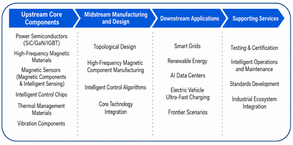
The development of the SST industry is driven by a coordinated industrial ecosystem characterized by:
- upstream suppliers establishing the technological foundation,
- midstream manufacturers controlling core system integration,
- downstream markets expanding application demand.
As technologies continue to mature and costs decline, SST applications are rapidly evolving from pilot projects to large-scale commercial deployment, driving transformation across multiple industries and becoming a critical enabler of next-generation power systems.
3.1 Core Industrial Chain Landscape
Upstream Core Components
Power semiconductor devices are the most critical components in SST systems, accounting for approximately 32% of total system cost. In medium- and high-voltage applications, SiC-based devices can represent as much as 40%–50% of the total component value.
IGBT technologies have already achieved relatively high localization rates in low- and medium-voltage markets in China, although some high-voltage, high-power modules still rely on imports. Domestic penetration of SiC and GaN devices currently stands at around 25%, and the localization rate of SiC MOSFETs is expected to increase to approximately 50% by 2026, while costs are projected to decline by roughly 30%.
Domestic substitution of high-frequency magnetic materials—including amorphous alloys and nanocrystalline materials—is also accelerating, with companies such as Hengdian Group DMEGC continuing to expand production capacity.
In addition, intelligent control ICs and thermal management materials have already achieved initial localization breakthroughs.
Current and voltage sensors are also fundamental sensing components for SST intelligent control and protection systems. These devices operate throughout the entire power conversion process, providing real-time data support for:
- closed-loop topology control,
- overcurrent and overvoltage protection,
- energy efficiency optimization.
They are therefore essential for achieving high-precision and highly reliable SST operation. Domestic companies such as Giant Magnet Intelligent have already introduced dedicated current sensor products specifically designed for high-frequency SST applications.
Supporting components such as intelligent control chips and thermal management materials are also seeing increasing domestic substitution, continuously strengthening supply chain independence and controllability.
Midstream Equipment Manufacturing
The key technological barriers in SST manufacturing are concentrated in:
- topology architecture design,
- high-frequency magnetic integration,
- intelligent control algorithms.
Industry participants can generally be divided into three categories:
| Company Type | Representative Enterprises | Core Competitive Advantages |
|---|---|---|
| Traditional Power Equipment Leaders | China XD Electric, CET Four-Faith | Strong industry experience, grid resources, and large-scale manufacturing capabilities |
| Power Semiconductor Companies Expanding into SST | StarPower Semiconductor | Advantages in core semiconductor technologies and vertical integration |
| Emerging Innovative Enterprises | CLOU Electronics | Agile innovation capabilities and specialized application development |
Core competitiveness across the industry is primarily concentrated in:
- R&D capability,
- production capacity,
- customer resources and ecosystem integration.
Downstream Application Scenarios
Demand for SST technology is expanding rapidly across multiple sectors, with the primary application areas including:
- smart grids,
- renewable energy systems,
- AI-driven data centers,
- EV charging infrastructure.
In the future, SST applications are expected to further expand into advanced frontier sectors such as:
- space-based power systems,
- deep-sea exploration infrastructure.
Meanwhile, supporting industries—including testing and certification services, as well as operation and maintenance ecosystems—are gradually becoming more mature, helping standardize and accelerate overall industry development.
3.2 Core Application Scenarios
As SST technologies continue to mature and system costs decline, application deployment is rapidly evolving from pilot demonstrations to large-scale commercialization. Current adoption is primarily concentrated in four key sectors:
- smart grids,
- renewable energy,
- AI-driven data centers,
- electric vehicle charging infrastructure.
In the future, SST applications are expected to further expand into advanced fields such as space power systems, deep-sea exploration, and distributed energy systems, creating substantial long-term market opportunities.
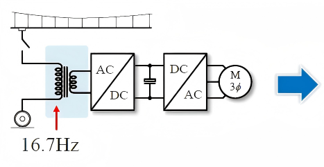
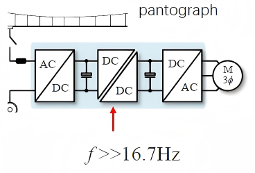
1. Traction Power Supply Systems
Challenges of Conventional Power-Frequency Traction Transformers
(mainstream 16.7 Hz systems in Europe)
- Transformer weight accounts for 12%–18% of total locomotive weight
- Power density is only 0.25–0.35 kVA/kg
- Space constraints result in excessive transformer current density
- Overall efficiency is limited to 89%–92%
SST-Based Solution
- Weight reduction of approximately 50%
- Power density increased to 0.5–0.75 kVA/kg
- Efficiency improvement of 2%–4%
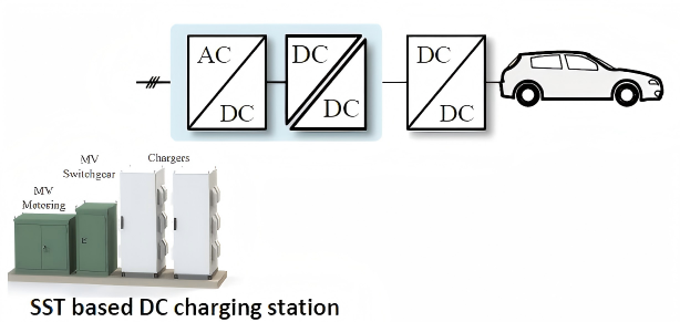
2. Electric Vehicle Charging Infrastructure
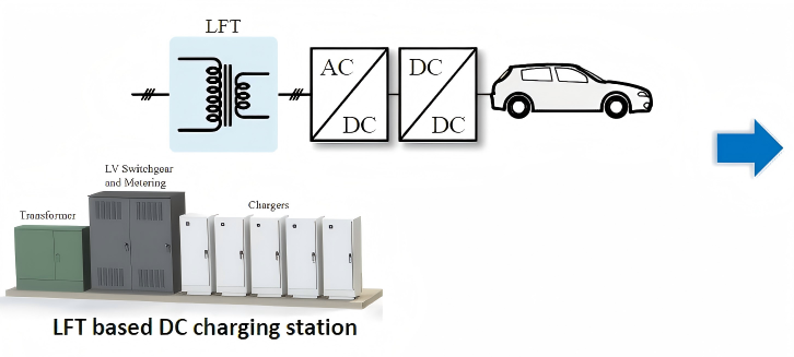
Challenges of Existing DC Fast Charging Stations
(power-frequency transformer + low-voltage interface cabinet + charging piles)
- Large installation footprint
- Fixed transformer capacity with limited scalability
- High current and high losses in low-voltage AC/DC conversion stages
- Grid-to-vehicle conversion efficiency below 95%
SST-Based Solution
- Modular architecture with flexible capacity expansion
- Eliminates conventional transformers and LV interface cabinets
- Footprint reduced by approximately 50%
- Improved AC/DC conversion efficiency, increasing overall efficiency by around 2%
3. Data Center Power Supply Systems
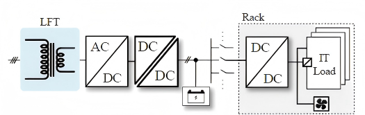
Challenges of Traditional Low-Voltage AC/DC Architectures
- High no-load losses in power-frequency transformers
- Large numbers of distributed power supply devices
- Power distribution areas can exceed 50% of total facility space
Example:
A 297 m² power distribution area containing:
- 34 power supply devices
- equipment from 4 different vendors
- 36 communication interfaces
- Low-voltage AC/DC conversion stages limit total system efficiency to only 95%–95.5%
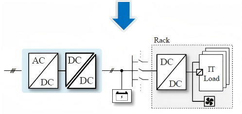
SST-Based Solution
- Modular architecture simplifies deployment and maintenance
- High integration significantly reduces equipment count
- Power distribution area reduced by approximately 63%
- Overall efficiency improved by 2%–3%
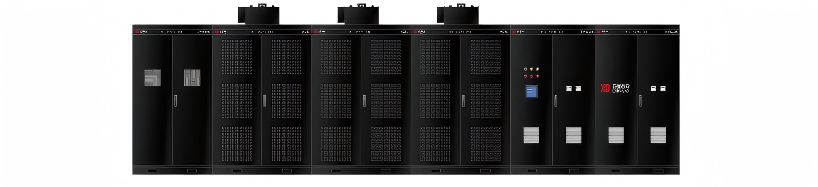
Case Study
A 2.4 MW data center SST developed by XJ Electric achieved a peak efficiency of 98%.
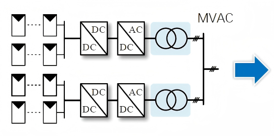
4. Medium-Voltage AC Grid-Connected Photovoltaic Systems
Challenges of Conventional Architectures
(PV string inverters + power-frequency transformers)
- No-load transformer losses during nighttime operation
- Combined inverter and transformer efficiency limited to approximately 96.5%
(98.5% inverter efficiency × 98% transformer efficiency) - Parallel operation of large numbers of inverters may lead to transient instability issues
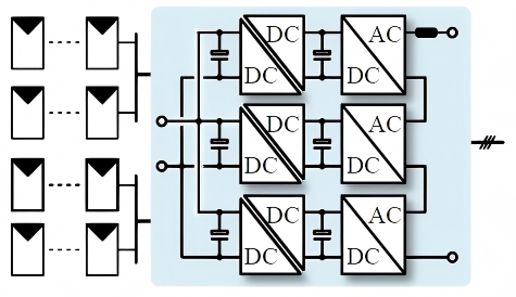
SST-Based Solution
- Lower no-load losses
- High integration and high power density
- Overall efficiency improvement of approximately 1%
Case Study
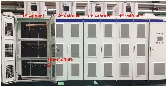
A 1 MW SiC-based MV grid-connected photovoltaic SST developed by TBEA achieved a peak efficiency of 98%.
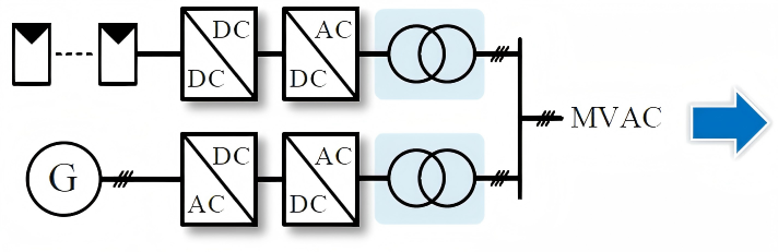
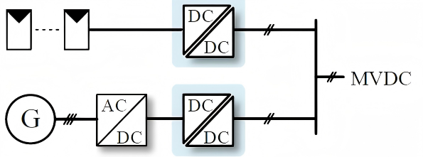
5. Medium-Voltage DC Collection for Renewable Energy Systems
Challenges of Conventional AC Collection Architectures
- Multiple power conversion stages and high-current operation reduce efficiency
- Significant losses in MV AC cable collection systems
- AC systems are vulnerable to harmonic distortion and resonance issues
Advantages of SST-Based DC Collection Architectures
- Integrated power conversion stages combined with soft-switching technologies reduce losses
- Medium-voltage DC cables provide lower transmission losses and higher collection efficiency
Case Study
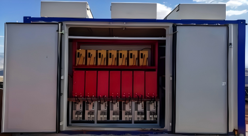
A ±30 kV / 1 MW photovoltaic DC step-up converter developed by the Institute of Electrical Engineering, Chinese Academy of Sciences.
6. Hybrid AC/DC Distribution Networks
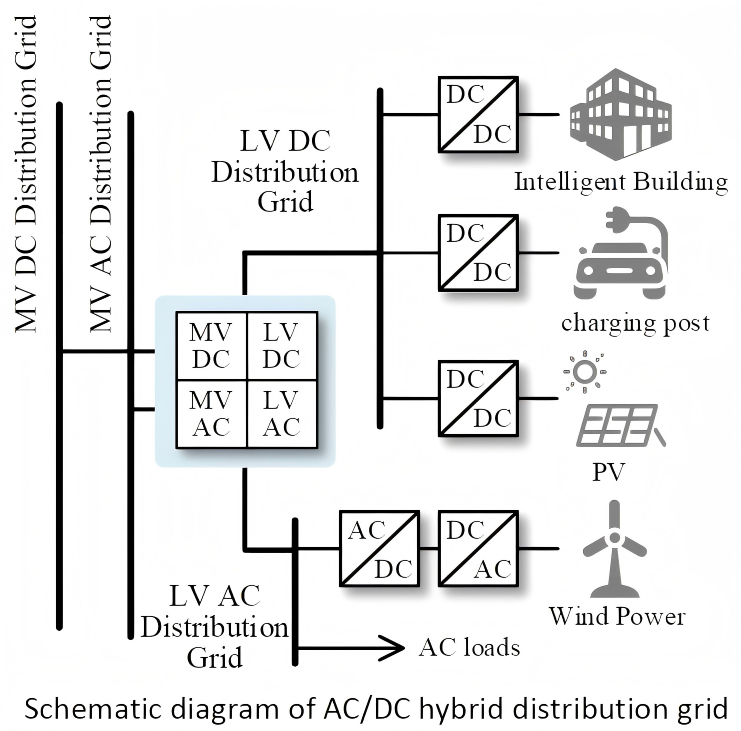
Characteristics of Hybrid AC/DC Distribution Networks
- Compatible with existing AC infrastructure
- Flexible integration of renewable energy and emerging load types
- Large numbers of AC/DC and DC/DC conversion stages
Functional Advantages of Multi-Port SST Solutions
- Integrated MV AC / MV DC and LV AC / LV DC interfaces
- Flexible voltage regulation across all ports
- Bidirectional energy interaction capability
- Reduced power conversion stages and improved overall efficiency
Case Studies
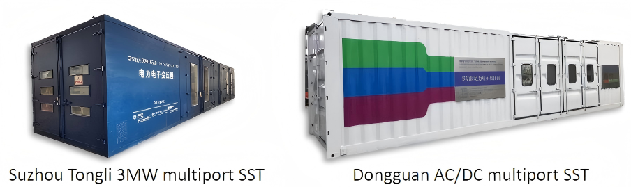
- 3 MW multi-port SST project in Tongli, Suzhou
- Multi-port AC/DC SST project in Dongguan
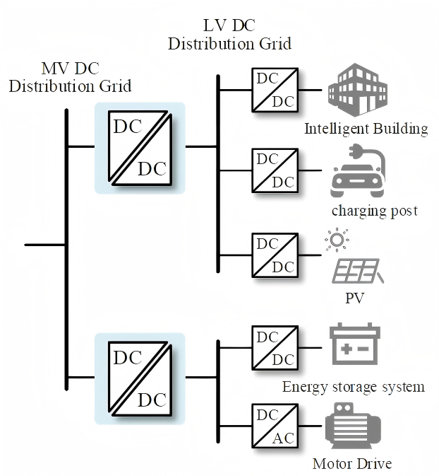
7. DC Distribution Networks
Characteristics of DC Distribution Networks
- Lower cable costs and higher transmission efficiency
- Efficient integration interface for renewable energy and energy storage systems
Core Role of SSTs (DC Transformers)
- The only viable technical approach for voltage conversion and energy interaction between MV DC and LV DC systems
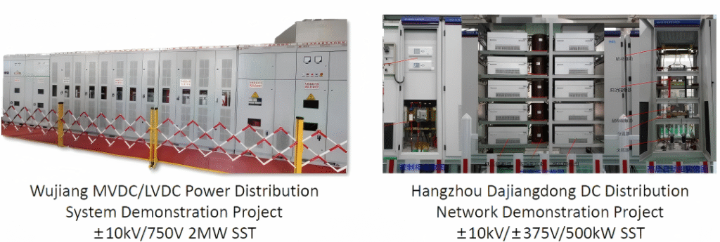
Case Studies
| Project | Specification |
|---|---|
| Wujiang Medium- and Low-Voltage DC Distribution Demonstration Project | ±10 kV / 750 V, 2 MW SST |
| Hangzhou Dajiangdong DC Distribution Demonstration Project | ±10 kV / ±375 V, 500 kW SST |
In the future, SSTs are also expected to play critical roles in advanced frontier applications such as space power systems and deep-sea exploration.
Space environments impose extremely strict requirements on equipment size and weight, making conventional transformers impractical. SSTs, with their compact structure and high reliability, can provide stable power supply solutions for space stations and interplanetary exploration systems, supporting the future of human space exploration.
3.3 Industry Transformation Value
Large-scale SST deployment will accelerate the transformation of power systems toward integrated coordination among:
- power generation,
- grid infrastructure,
- loads,
- energy storage.
This transition will:
- support renewable energy as a primary energy source,
- empower the digital economy and advanced manufacturing industries,
- drive coordinated upgrades across the entire industrial chain.
Ultimately, the industry is expected to form a new development landscape characterized by:
- upstream technological breakthroughs,
- midstream industrial expansion,
- downstream application explosion.
IV. Conclusion: SSTs Are Reshaping the Energy Landscape, with Giant Magnet Intelligent Enabling Reliable Performance
With advantages including high efficiency, compact size, and intelligent controllability, Solid-State Transformers (SSTs) are overcoming the limitations of conventional transformers and rapidly becoming a core enabling technology for next-generation power systems. Their development is driving coordinated upgrades across the industrial chain while empowering growth in renewable energy, AI infrastructure, transportation, and many other industries.
The stable and efficient operation of SST systems relies heavily on one critical sensing component: the current sensor. In many ways, current sensors serve as the “precision eyes” of SST systems—and this is where the current sensing solutions from Giant Magnet Intelligent play a vital role.
As a nationally recognized “Little Giant” specialized and innovative enterprise, Giant Magnet Intelligent has developed deep expertise in electromagnetic sensing and control IC technologies. Its portfolio of current sensors offers:
- high sensitivity,
- high accuracy,
- microsecond-level response speed.
These capabilities enable precise detection of high-frequency and ultra-small current fluctuations within SST systems, providing reliable real-time data support for:
- system control,
- protection mechanisms,
- energy efficiency optimization.
The products are specifically designed to match the high-frequency operating characteristics of modern SST architectures.
From the growing limitations of conventional transformers to the rapid rise of SST technology, the transformation of the energy conversion industry is now fully underway. Guided by its product philosophy of practicality, speed, and continuous innovation, Giant Magnet Intelligent will continue aligning its technologies with the evolving needs of the SST industry.
Together with the advancement of SST technologies, the company aims to unlock new paradigms of efficient energy utilization, support the high-quality development of China’s energy industry, and accelerate the transition toward a smarter, more efficient, and greener energy future.