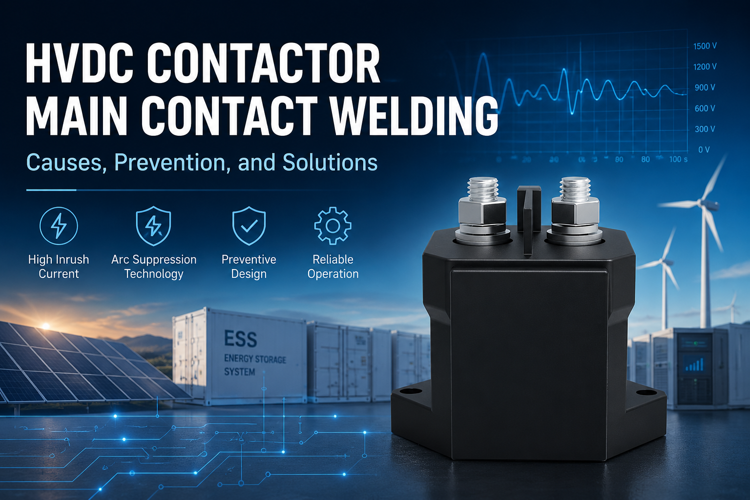
In PV, energy storage, and EV charging systems, high-voltage DC (HVDC) contactors are critical electrical components that ensure safe and reliable system operation. They are widely used in battery energy storage systems (BESS), EV charging stations, PV inverters, and DC distribution systems.
As system voltage and power levels continue to increase, HVDC contactors must withstand high voltage, high current, and frequent switching operations while also delivering excellent DC breaking capability and anti-welding performance.
Among all failure modes, main contact welding is one of the most common and dangerous issues in HVDC contactors. Once contact welding occurs, the contactor may fail to disconnect, potentially causing equipment damage, system short circuits, or even severe safety incidents.
This article provides a systematic engineering analysis of the major causes of HVDC contact welding, along with practical prevention methods and technical solutions.
1. Application Characteristics of HVDC Contactors
Compared with conventional AC systems, DC systems place significantly higher demands on contactors.
HVDC contactors typically operate under the following conditions:
- High operating voltage (hundreds of volts up to 1500VDC)
- High current loads (tens to hundreds of amperes)
- Frequent switching operations
- Capacitive or inductive load surges
- Long-duration continuous operation
In DC systems, there is no natural current zero-crossing as found in AC systems, meaning electrical arcs cannot extinguish naturally. As a result, sustained arcing is much more likely during contact separation.
The extreme heat generated by these arcs rapidly erodes contact materials and, in severe cases, melts and permanently bonds the main contacts together — commonly referred to as contact welding.
2. Main Causes of HVDC Main Contact Welding
2.1 High Inrush Current from Capacitive Loads
In energy storage systems, PV inverters, and DC bus applications, large filter capacitors or support capacitors are commonly used.
When the contactor closes, uncharged capacitors initially behave like a short circuit, generating extremely high inrush current.
RC time constant:
τ=RC
Capacitor charging current equation:
I(t)=e−t/R
In real-world systems, instantaneous inrush current may reach dozens of times the rated operating current.
When such large current flows through contacts that are not yet fully closed, severe arcing and substantial Joule heating occur.
Joule’s Law:
Q = I^2Rt
Localized overheating can rapidly melt the contact surface material. Once the contacts fully close, the molten metal resolidifies, eventually causing contact welding.
Example
In a 1500V energy storage system, large DC bus capacitors may generate several hundred amperes of inrush current during startup, placing enormous stress on the contactor.
2.2 Contact Overheating Caused by Overload Operation
Long-term overload operation is another major cause of contact welding.
When the actual operating current exceeds the contactor’s rated current, contact resistance generates continuous heat buildup.
As temperature rises:
- Contact materials gradually soften
- Contact resistance further increases
- Arcing becomes more likely
- Contact erosion accelerates
Eventually, the contact surface may melt or weld together.
In PV-storage-charging systems, overload conditions commonly result from:
- High-rate charge/discharge operation in energy storage systems
- High-power DC fast charging
- Battery fault conditions
- Insufficient thermal management
2.3 Short-Circuit Current Impact
When a system short circuit occurs, current rises dramatically within an extremely short time.
The thermal effect of short-circuit current is commonly expressed as:
I^2t
Massive short-circuit current generates not only severe thermal shock, but also strong electrodynamic force that mechanically compresses the contacts.
In low-impedance energy storage systems, short-circuit current may instantly reach several thousand or even tens of thousands of amperes, severely impacting both the contact system and the arc extinguishing structure.
Even if the contactor successfully interrupts the fault current, the extreme arc temperature may still cause severe contact erosion or welding.
Common causes of short circuits include:
- Internal battery pack faults
- Cable insulation failure
- DC bus short circuits
- Loose connectors or conductive foreign objects
2.4 Arc Accumulation Caused by Frequent Switching
Frequent opening and closing operations repeatedly generate electrical arcs.
For inductive loads, disconnecting current can also produce high reverse induced voltage, extending arc duration even further.
Since DC arcs do not naturally extinguish, local arc temperatures can reach several thousand degrees Celsius — high enough to melt most contact materials.
Long-term arc exposure may lead to:
- Contact material erosion
- Roughened contact surfaces
- Increased contact resistance
- Higher welding risk
This issue is particularly common in:
- Frequent charge/discharge switching in energy storage systems
- Power switching in EV chargers
- Grid-tied/off-grid switching in PV systems
2.5 Environmental Factors
Harsh operating environments can also reduce contactor reliability.
Key factors include:
Vibration
Mechanical vibration may cause the contacts to remain in a “partial contact” state, resulting in continuous arcing.
Poor Heat Dissipation
Insufficient cooling in enclosed spaces can lead to excessive temperature rise.
Dust and Moisture
Contaminants increase contact resistance and create localized heating.
Extreme Temperature Conditions
High temperatures reduce contact hardness, while low temperatures may cause material embrittlement.
3. Key Measures to Prevent Main Contact Welding
3.1 Pre-Charge Circuit Design
For capacitive load systems, a pre-charge circuit is one of the most effective anti-welding solutions.
A typical pre-charge sequence is as follows:
- The pre-charge contactor closes
- Current charges the capacitor gradually through the pre-charge resistor
- Capacitor voltage gradually approaches bus voltage
- The main contactor closes
- The pre-charge circuit disconnects
The minimum pre-charge resistor value can generally be estimated as:
R≥V/I
Example
In a 1500V system, if the pre-charge current must remain below 100A, the pre-charge resistor should exceed 15Ω.
In practical designs, engineers must also consider:
- Capacitance value
- Allowed pre-charge time
- Resistor power rating
- Overall system efficiency
Typical pre-charge duration ranges from tens to hundreds of milliseconds.
Additional critical concerns include:
- Pre-charge relay failure
- Open-circuit pre-charge resistor
- BMS control malfunction
- Main contact closure before pre-charge completion
All of these conditions can significantly increase the risk of contact welding.
3.2 Proper Contactor Selection
Improper contactor selection is one of the most common causes of welding failures.
Voltage Margin
The contactor’s rated voltage should generally be at least 120% of the system operating voltage.
Example
For a 1500V system, an 1800V-rated contactor is recommended.
Current Margin
A current safety margin of 30%–50% is recommended.
Example
For a 100A load, selecting a 130A–150A contactor is advisable.
Utilization Category
The appropriate DC utilization category should be selected according to load characteristics:
- DC-1: Resistive or slightly inductive loads
- DC-21B: Mixed resistive-inductive loads
- DC-3: Motor-type loads
Energy storage and PV systems typically require additional validation based on actual operating conditions.
Contact Materials
High-performance composite materials can significantly improve anti-welding capability.
Common materials include:
- AgSnO₂ (Silver Tin Oxide)
- AgWC (Silver Tungsten Carbide)
Compared with pure silver contacts, these materials offer:
- Better anti-welding performance
- Higher arc erosion resistance
- Improved high-temperature stability
3.3 Arc Extinguishing System Optimization
Since DC arcs are difficult to extinguish, arc suppression system design is especially important.
Common solutions include:
Magnetic Blowout Arc Suppression
Magnetic fields force the arc to move and elongate, enabling faster cooling and extinction.
Multi-Break Contact Design
Increasing the number of breaking points raises the total arc voltage drop.
Vacuum Arc Extinguishing Technology
Vacuum environments significantly improve DC interruption capability.
RC Snubber Circuits
Reduce voltage spikes generated by inductive loads.
Freewheeling Diodes
Minimize arc impact caused by reverse induced voltage.
4. Handling Methods After Main Contact Welding
4.1 Emergency Power Isolation and Safety Procedures
After contact welding occurs, the following actions should be taken immediately:
- Disconnect system power
- Safely discharge capacitors
- Implement LOTO (Lockout/Tagout) procedures
- Prohibit live maintenance operations
For high-voltage energy storage systems, ensure the DC bus voltage is fully discharged before servicing.
4.2 Inspection and Fault Diagnosis
Key inspection items include:
- Contact erosion condition
- Arc chamber damage
- Coil condition
- Main circuit insulation integrity
- Signs of short-circuit damage
Recommended diagnostic tools include:
- Multimeters
- Insulation resistance testers
- Infrared thermal imaging cameras
4.3 Replacing Contacts or the Contactor
If severe welding has occurred, the contacts or the entire contactor should be replaced.
During replacement, ensure:
- The replacement product matches original specifications
- Wiring torque is correctly applied
- Contact pressure consistency is verified
- Arc extinguishing components remain intact
- Conduction and interruption performance are re-tested
5. Maintenance and Preventive Management
5.1 Regular Thermal Inspection
Periodic infrared thermal inspection is recommended for:
- Contact temperatures
- Terminal temperatures
- Busbar connection points
Any abnormal temperature rise should be addressed immediately.
5.2 Mechanical and Electrical Life Management
HVDC contactors typically have both:
- Mechanical life expectancy
- Electrical life expectancy
As switching cycles increase:
- Arc erosion gradually accumulates
- Contact thickness continuously decreases
- Contact resistance steadily rises
Therefore, regular inspection of contact wear is essential.
In general, replacement should be considered when contact thickness falls below 50% of its original value.
5.3 Environmental Management
To reduce contactor failure risk, the following conditions should be maintained whenever possible:
- Proper ventilation
- Dust and moisture protection
- Minimal vibration exposure
- Controlled ambient temperature
6. Future Development Trends of HVDC Contactors
Driven by rapid growth in energy storage, EVs, and the photovoltaic industry, HVDC contactors are evolving toward:
- Higher breaking capacity
- Longer electrical life
- Lower power consumption
- Smaller size
- Intelligent condition monitoring
- Higher safety standards
In the future, intelligent HVDC contactors integrating temperature sensing, current monitoring, and lifetime prediction capabilities are expected to become a major industry trend.
7. Conclusion
Main contact welding in HVDC contactors is a typical failure mode in PV-storage-charging systems. Its root causes are generally related to capacitive inrush current, short-circuit impact, accumulated arc energy, and improper contactor selection.
Because DC systems lack a natural zero-crossing point, arc extinction becomes far more challenging. As a result, HVDC contactors place much higher demands on arc suppression design, contact materials, and system-level pre-charge control.
In engineering practice, properly designed pre-charge circuits, correct contactor utilization category selection, and optimized thermal/protection systems are key measures for reducing contact welding risk.
Meanwhile, temperature monitoring, preventive maintenance, and lifecycle management can significantly improve long-term system reliability.
As the energy storage, photovoltaic, and EV industries continue to expand, HVDC contactors will continue evolving toward higher interruption capability, longer service life, and smarter condition monitoring technologies.