In applications such as AC charging piles and the grid-connected side of inverters, the leakage current sensor RCMU is usually used together with relays and arranged in close proximity. However, the operating characteristics of relays may interfere with the RCMU device. Especially in charging pile products, such interference may cause the product to fail relevant leakage current detection standards, thus affecting the product development schedule. To avoid such issues, all related factors need to be fully considered during the design stage.
In practical applications, a type of abnormal behavior may occur in RCMU devices, including false triggering and excessively long triggering time. The first is false triggering, where the RCMU incorrectly initiates a protection action when there is no real leakage current fault or when the leakage current has not reached the threshold. The second is abnormal triggering time, including significantly slower response speed or action time exceeding the design specifications. These abnormal phenomena are often intermittent, making troubleshooting more difficult.
Such problems are very likely unrelated to the device itself. When the RCMU is removed and tested separately, all its performance indicators are normal. In some prototype boards, even after removing the RCMU, fluctuations can still be observed on the leakage detection output pin. This indicates that such faults are actually caused by other design factors on the entire board.
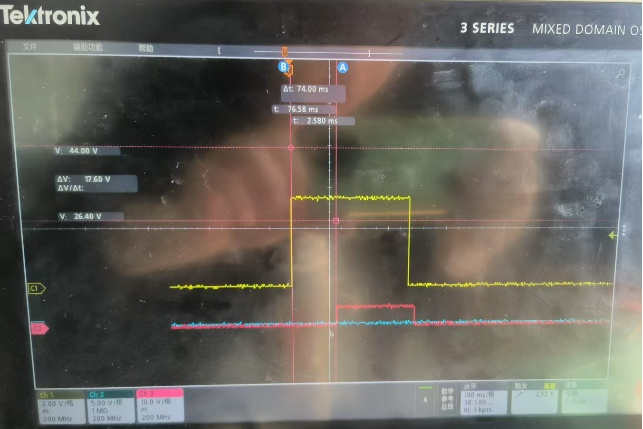
RCMU excessive triggering time fault
Yellow: leakage current waveform, Red: detection output waveform
Actual investigation shows that such faults are often related to relays on the board, mainly including common-mode interference and magnetic field interference.
At the moment when the relay closes, a large common-mode interference is generated. When the relay contacts close, the current in the relay circuit rises instantaneously, resulting in a large di/dt. Considering the parasitic inductance in the circuit, a large interference voltage will be induced in the loop, i.e., V = L * di/dt. At the same time, according to Faraday’s law of electromagnetic induction, this rapidly changing electric field generates an alternating magnetic field, which further propagates interference to nearby circuits, forming common-mode interference. In actual testing, the most obvious characteristic of relay-induced common-mode interference is simultaneous fluctuations in the power supply, unrelated signals, and even ground.
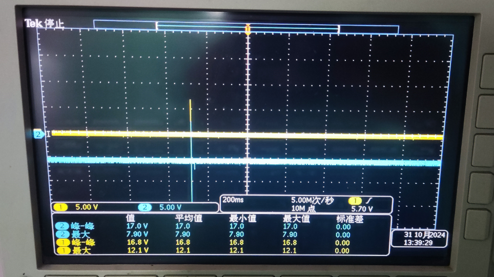
Captured transient waveform showing simultaneous fluctuation of power supply and ground on site
In addition, the operation of the relay itself generates a relatively strong magnetic field, which may affect magnetically sensitive devices. The working principle of a relay is to energize an electromagnet, thereby closing the contacts and conducting the high-power circuit. Therefore, when the relay is closed, its internal electromagnet radiates a magnetic field outward. For commonly used isolated current detection devices such as fluxgate RCMUs and Hall sensors, their detection principle is based on sensing magnetic fields generated by current, so the magnetic field from the relay will also affect their operation.
To avoid interference from relays, the following solutions can be considered in design:
1、Component placement optimization
During the PCB layout design stage, special attention should be paid to the relative positions of the relay and the RCMU device. The following measures are recommended: first, ensure a certain physical distance between the two to effectively attenuate magnetic field strength; second, avoid placing the RCMU directly above or below the relay, because the magnetic field attenuates more slowly along the axial direction; finally, a horizontal side-by-side layout is recommended, and magnetic shielding measures can be added if necessary.
2、PCB layout optimization
Try to shorten the routing length of the relay high-power circuit as much as possible and avoid sensitive signal lines. At the moment the relay closes and interference is generated, the common-mode interference radiates outward with the loop acting as an antenna. Therefore, shortening the loop length can effectively reduce the radiation range of common-mode interference. Placing the high-power circuit away from low-power signal circuits and ensuring proper isolation can also effectively prevent interference to weak signals.
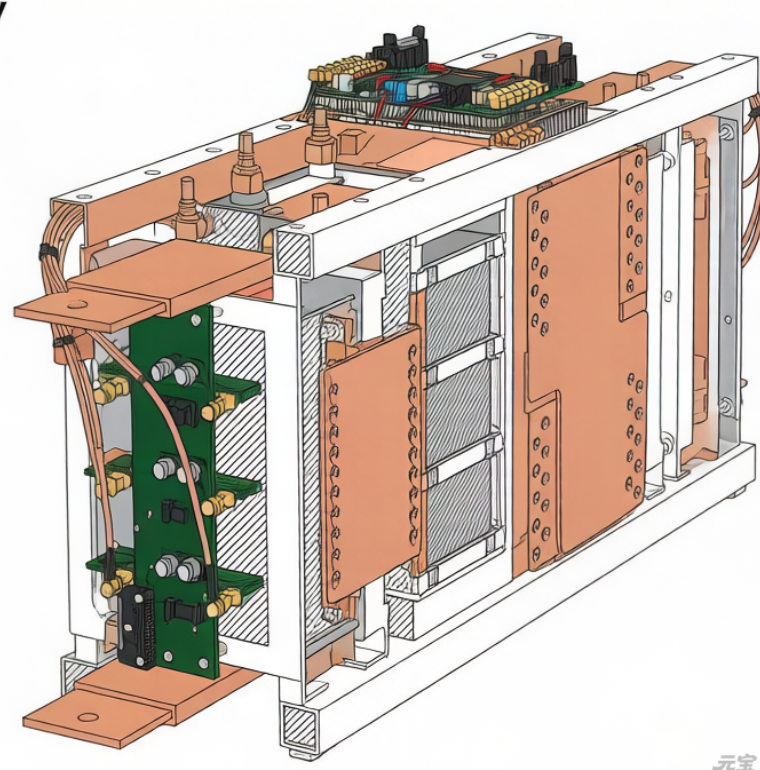
As shown in the figure below, the relay routing is relatively long and located close to low-power circuits such as the microcontroller. Common-mode interference issues were observed during actual testing.
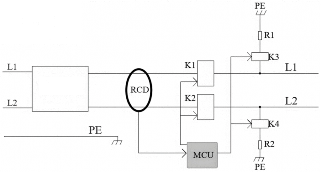
3、Adding suppression circuits
To suppress the rise of common-mode voltage, RC circuits, diodes, TVS devices, and other components can be added to form suppression circuits. The figure below introduces various suppression circuits and their application characteristics. Some relays have built-in suppression circuits; if these circuits fail, they may also cause abnormal behavior of the RCMU device.
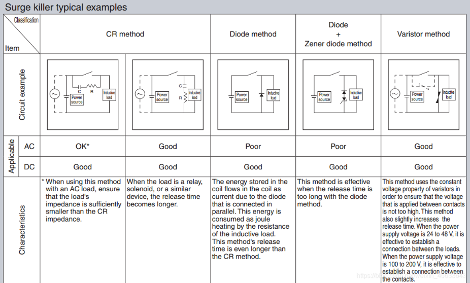
Relay suppression circuit design