European regulations for EV charging infrastructure impose stringent requirements on standards and certification. This paper explores how different IEC residual current standards can be applied to meet these requirements while reducing design complexity and cost.
Through a detailed analysis of mechanical coupling, electronic coupling, residual current detection, and control circuitry defined in the standards, a feasible solution is proposed. We welcome further discussion and feedback from readers.
2.Theoretical Framework – EV Charging Standards
With the rapid adoption of electric vehicles, safety and compatibility of charging infrastructure have become increasingly critical. Europe, known for its rigorous regulatory framework, serves as a global benchmark in this domain.
The region hosts leading automotive manufacturers and top-tier suppliers, demonstrating strong industrial capabilities. During the current transition toward electrification, both EVs and their supporting infrastructure are expanding rapidly.
European standards are widely recognized and trusted globally. Not only must exported products comply with these standards, but even domestic standards in other regions often reference them.
For residual current detection in EV charging stations, IEC 62955 is commonly applied for Mode 3 charging systems, specifying requirements for residual direct current detecting devices (RDC-DD).
2.1 IEC 62955 – Residual Direct Current Detecting Device (RDC-DD)
IEC 62955 defines electrical and control requirements for conductive EV charging systems. It specifies detailed requirements for:
Mechanical design
Protective measures
Insulation characteristics
Temperature rise limits
Operational performance
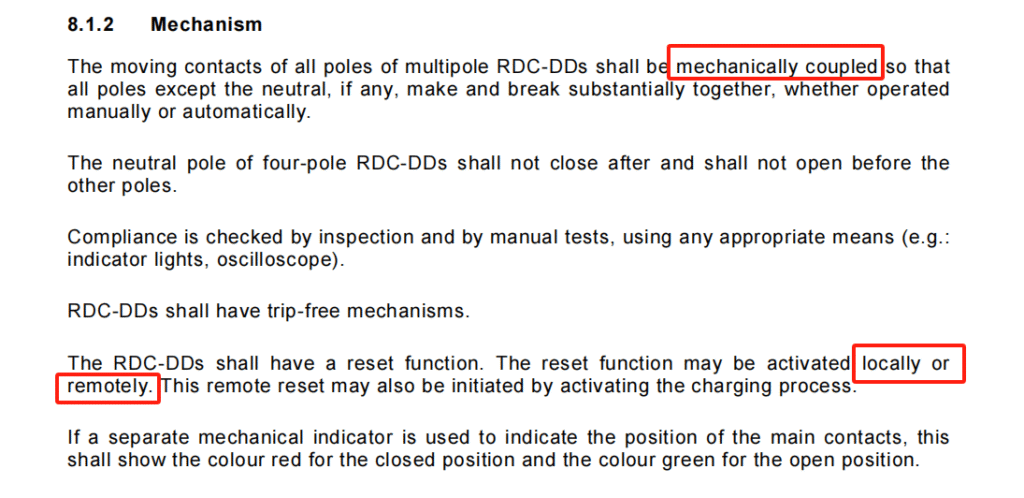
From a mechanical perspective, the standard requires RDC-DD modules to include a mechanical disconnection function via coupling.
This means the RDC-DD must be capable of mechanically triggering an associated protective device (e.g., circuit breaker or RCD) to disconnect the circuit when residual DC current exceeds a threshold.
Such mechanical coupling (e.g., via linkages or gears) ensures reliable disconnection but significantly increases design complexity and cost.
Electronic Coupling Alternative
The standard also allows an electronic coupling approach, where disconnection is controlled via electrical signals.
In this case:
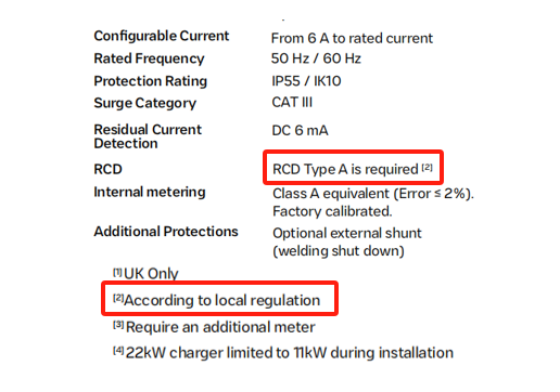
A Type A RCD is required
The system must disconnect when DC residual current exceeds 6 mA
However, Type A RCDs remain relatively costly compared to breakers or relays.
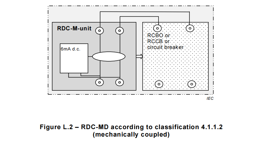
The standard also permits a configuration using:
Current transformer (CT) + circuit breaker/relay, which can serve as an alternative Type A protection solution:
RDC-M module + circuit breaker/relay
Cost-Optimized Design Approach
The RDC-M + relay solution offers:
Reduced design complexity
Lower cost
However, it still requires a Type A RCD. To minimize cost, manufacturers often specify that:
A Type A RCD should be installed on the upstream distribution side in accordance with local regulations.
2.2 IEC 60947-2 – Low-Voltage Switchgear and Controlgear
The preference for mechanical coupling in standards reflects:
Reliability considerations
The need for manual reset capability for safety
Strictly speaking, Type A RCD protection is essential and cannot be fully replaced, particularly to prevent “blinding” effects caused by DC residual currents.
Role of IEC 60947-2:2024
IEC 60947-2:2024 defines requirements for low-voltage switchgear, including residual current protection in:
Annex M (MRCD – Modular Residual Current Devices)
While Annex M specifies technical requirements for residual current protection, it does not explicitly mandate a specific coupling method.
This implies:
Both mechanical and electronic coupling are acceptable
Designers can choose simpler electronic coupling solutions
Reliability and Failure Verification
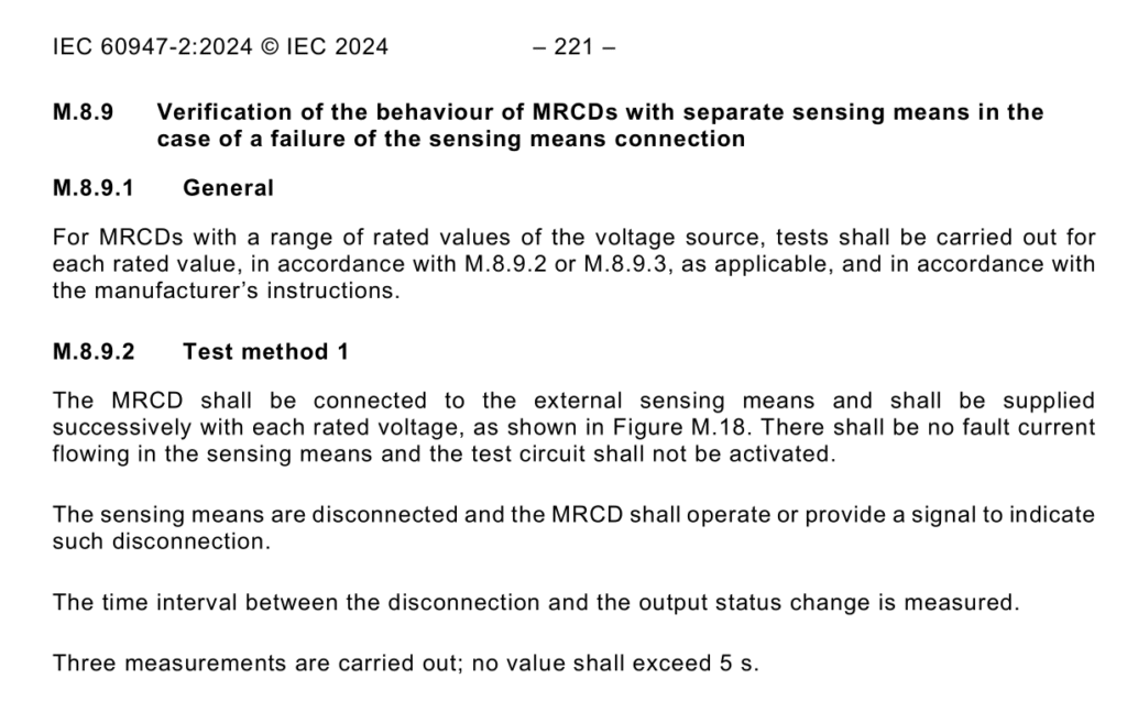
To ensure safety, Annex M includes:
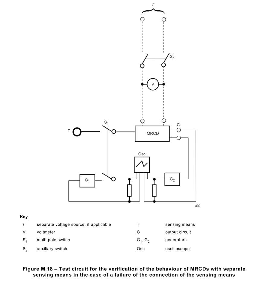
Failure mode verification (M.8.9)
Self-test–like mechanisms to detect abnormal connections
These tests verify whether the RCD can:
Detect faults
Reliably disconnect the circuit under abnormal DC residual current conditions
Residual Current Requirements
In EV charging applications, residual current protection typically follows:
IEC 61008 + IEC 62955 (Type A + 6 mA DC detection)
However, IEC 60947-2:2024 does not explicitly define this combination.
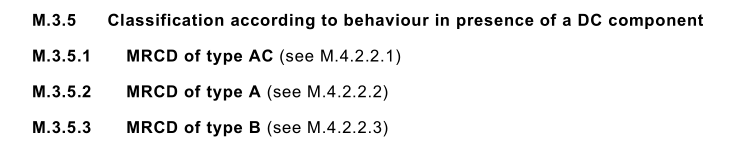
Instead, Annex M classifies devices into:
Type AC
Type A
Type B
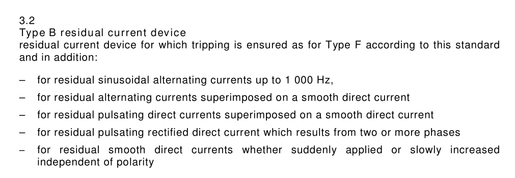
For EV charging systems, Type B is generally required.
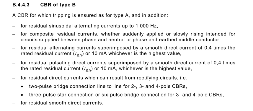
Type B Testing
Although Annex M does not directly reference other standards for Type B testing, Annex B.4.4.3 provides an independent description.
Comparison shows alignment with:
IEC 62423:2009
This confirms that IEC 60947-2 effectively incorporates equivalent Type B testing requirements.
3. Conceptual Model
Although European standards for EV charging are stringent, a balanced approach can be achieved by considering:
Standards compliance
Design complexity
Cost optimization
Adopting IEC 60947-2 for Type B residual current detection may:
Reduce certification constraints
Lower design complexity and cost
This approach remains open for further industry discussion.
Design Philosophy
Choosing IEC 60947-2 does not compromise safety. Instead, it provides:
Greater design flexibility
Faster adaptation to market demands
Compatibility across different regions and applications