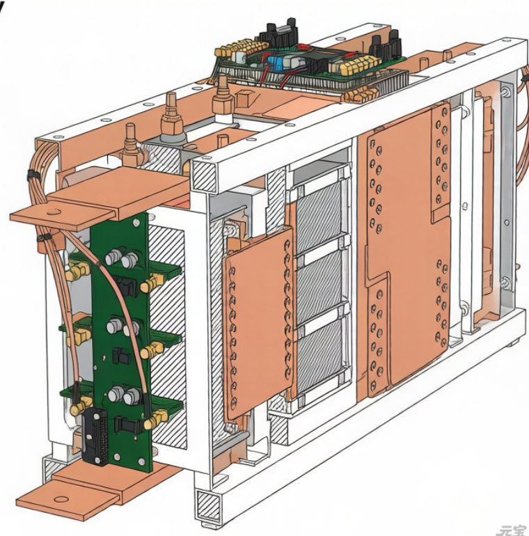
In the power topology of photovoltaic inverters, voltage sensors face more severe common-mode stress environments than current sensors. When SiC/GaN devices switch at speeds of tens of kV/µs, the extremely high common-mode voltage change rate (dv/dt) generated between the power loop and the reference ground causes devastating interference to millivolt-level useful differential voltage signals through parasitic coupling paths of the sensor and its signal chain. This problem is particularly prominent at key measurement points such as string voltage detection, DC bus voltage sampling, and midpoint potential balance. The resulting measurement distortion directly threatens the accuracy of Maximum Power Point Tracking (MPPT), the stability of DC bus voltage, and the safe operation of three-level topologies. This paper will deeply analyze the common-mode noise injection mechanism in high dv/dt environments, reveal the failure boundaries of traditional differential amplification and isolated sampling schemes, and systematically discuss advanced voltage sensing architectures based on active common-mode cancellation, real-time transmission line modeling, and digital dynamic compensation.
I. Intrusion Paths of High dv/dt Common-Mode Noise and Failure of Classical Measurement Architectures
At the moment of power device switching, the voltage between its drain and the heatsink jumps. This jumping voltage couples to the entire system through stray capacitance.
1.1 Three Core Intrusion Paths of Common-Mode Noise
Path 1: Common-mode impedance of the sensor power supply. Isolated power supplies that power voltage divider networks or isolation amplifiers have parasitic capacitance between the primary and secondary sides. This current flows through the power supply internal resistance and PCB ground impedance, generating common-mode voltage fluctuations on the “clean” power ground of the sensor.
Path 2: Parasitic capacitance coupling of the voltage divider resistor network. The resistor divider that detects high-voltage DC bus or string voltage has distributed capacitance between its high-voltage end and the surrounding grounded chassis or heatsink. The displacement current generated by dv/dt across this capacitance is directly injected into the voltage divider network, superimposed on the DC voltage to be measured, forming high-frequency noise. More seriously, this current generates a voltage drop across the parasitic inductance of the voltage divider resistor itself, causing frequency-dependent distortion of the voltage division ratio.
Path 3: Antenna effect of signal transmission lines. The signal traces from the sensor output to the controller form parasitic capacitance with the power busbar or switch nodes. This capacitance and the trace inductance form an LC resonant circuit. dv/dt excites this circuit, inducing damped oscillatory common-mode noise on the signal line with a frequency up to hundreds of MHz, which can easily cause false triggering of the comparator at the receiving end or abnormal jumps in ADC sampling values.
1.2 Failure Boundaries of Traditional Isolation Amplifiers and Differential Amplifiers
Frequency attenuation of Common-Mode Rejection Ratio (CMRR) in isolation amplifiers: As the frequency increases, the parasitic capacitance of the isolation barrier becomes dominant, and the actual CMRR may decrease at the switching frequency and its harmonics. This means that a 1000V, 50kV/µs common-mode interference can generate an equivalent differential input error at 100kHz that is sufficient to completely overwhelm the real voltage signal.
Input asymmetry disaster of differential amplifiers: The CMRR of differential amplifiers relies on the absolute symmetry of their two input paths. However, it is difficult to achieve complete consistency in the parasitic capacitance to the chassis of the two input traces connected to the high-voltage divider. Even a difference of only 0.1pF will generate an unbalanced common-mode current of 5mA under a dv/dt of 50kV/µs. This current flows through the input resistor and is directly converted into an unavoidable differential error voltage.
II. Specific Impacts of Measurement Distortion on System Performance and Safety
The resulting voltage measurement error is not simply “inaccurate reading” but can cause systematic functional disorders.
2.1 The “Fog” of MPPT Algorithms and the “Oscillation” of DC Bus Voltage
MPPT decision confusion: String voltage is the core input of the MPPT algorithm. The severe fluctuations of sampling values within the switching cycle caused by common-mode noise make it impossible for the algorithm to accurately calculate power P. The perturb and observe method misjudges noise as a power change trend, leading to the operating point randomly wandering around the maximum power point, with an average efficiency loss of up to 1-2%.
DC bus voltage loop instability: The DC bus voltage closed loop is the cornerstone of inverter stability. High-frequency common-mode noise makes the sampling value contain false harmonic components. When the bandwidth of the voltage loop is designed to be high, the controller will attempt to “correct” these non-existent voltage fluctuations, and instead inject disturbances of the corresponding frequency into the modulation wave. This disturbance is amplified by the power circuit, which may excite resonance with the input filter or grid impedance, leading to actual oscillation of the bus voltage.
2.2 The “Collapse” of Midpoint Potential Balance in Three-Level Topologies
In T-type or NPC three-level topologies, the balance of the voltage across the upper and lower DC bus capacitors is crucial, determined by the direction and magnitude of the midpoint current. The measurement sensors share the same high-voltage reference point but withstand switch dv/dt of opposite phases. Due to the asymmetry of parasitic parameters, the common-mode interference suffered by the two is completely different. This causes the voltage unbalance observed by the controller to deviate significantly from the true value. The balance algorithm based on this incorrect observation will issue wrong compensation commands, which not only fail to balance the midpoint but may also accelerate its drift, eventually leading to capacitor overvoltage or device overstress.
2.3 False Alarms and Missed Alarms of Insulation Monitoring Devices (IMD)
Active Insulation Monitoring Devices (IMD) evaluate insulation resistance by injecting test signals and measuring responses. Their injection and measurement circuits are also exposed to system common-mode noise. Strong switching dv/dt may be falsely captured by the IMD as a response signal of insulation failure, leading to frequent false alarms. Conversely, the real weak insulation fault signal may be completely submerged by common-mode noise, resulting in missed alarms.
III. Systematic Voltage Sensing Solutions for High dv/dt Environments
Solving this problem requires systematic innovation from the sensor front-end, transmission path to processing algorithms.
3.1 Active Common-Mode Cancellation and Local Digitization at the Sensor Front-End
Active shield driving technology: Add a “shielding layer” driven by a buffer amplifier to the voltage divider resistor network or sensor input terminal. This driving signal actively follows the change of the local common-mode potential, maintaining the potential difference across the parasitic capacitance of the voltage divider network to ground close to zero, thereby theoretically eliminating the injection of displacement current through this capacitance. This requires the driving amplifier to have sufficient bandwidth and slew rate to track high-frequency dv/dt.
Local Σ-Δ ADC conversion and digital isolation: Place a high-resolution Σ-Δ ADC as close as possible to the high-voltage voltage division point to complete the analog-to-digital conversion at the first site of noise injection. Then, transmit the digital bitstream through a capacitive or magnetic coupling digital isolator. This fundamentally cuts off the path of high-frequency common-mode noise propagation through the analog signal link.
3.2 Impedance-Controlled Design and Differential Reconstruction of Transmission Paths
Use twisted-pair shielded cables and terminate them correctly: For cases where analog signals must be transmitted, force the use of twisted-pair shielded cables. The shielding layer must be connected to the reference ground of the measured high voltage at a single point on the sensor side to discharge common-mode current. At the receiving end, use a differential receiver with high input impedance and good high-frequency common-mode rejection, and consider a termination resistor according to the length of the transmission line to prevent reflection.
Pseudo-differential measurement and software reconstruction: When measuring a single-ended high voltage, an additional “dummy” sensor can be added. This sensor is connected to a reference point with similar dv/dt characteristics to the measured point but no useful signal. The output of the main sensor and the output of the dummy sensor are sampled simultaneously. The latter only contains common-mode noise information. Through digital subtraction, common-mode rejection far exceeding the capability of hardware circuits can be achieved in software.
3.3 Dynamic Compensation Based on Real-Time Models and Adaptive Filtering
Establish a sensor system SPICE model including parasitic parameters: Accurately extract key parasitic parameters through simulation and actual measurement. Run a simplified model in real-time in the controller to predict the transient waveform of common-mode noise according to the current switching state and bus voltage.
Adaptive notch filtering and synchronous sampling: Dynamically adjust the center frequency of the digital notch filter according to the predicted noise spectrum. At the same time, strictly synchronize the ADC sampling time to the “quiet period” of the switching noise to avoid the moment when the noise amplitude is maximum.
IV. Conclusion: Cognitive Upgrade from “Measurement Circuit” to “Electromagnetic Compatibility System”
Voltage measurement in photovoltaic inverters has evolved into a war of extracting weak signals in extreme common-mode environments. The traditional linear thinking of “voltage division – isolation – amplification – sampling” has failed in the face of dv/dt as high as tens of kV/µs. The root cause of the problem is that the differential voltage signal we are trying to measure cannot be completely decoupled physically from the violently changing common-mode electromagnetic field in which it is located.
Therefore, the new generation of design philosophy must regard the voltage sensing channel as a complete “electromagnetic compatibility subsystem”. Its design starting point is no longer the accuracy indicators in the data sheet, but the quantitative evaluation of the electromagnetic environment at the installation location, the modeling and control of each parasitic coupling path, and the active utilization and avoidance of the time-domain and frequency-domain characteristics of noise. This requires an unprecedented deep integration of PCB layout, shielding design, isolation technology, and signal processing algorithms.
Ultimately, achieving accurate and reliable voltage sensing no longer relies solely on a high-performance isolation amplifier chip, but on a complete set of systematic collaborative designs from the shape of the sensor probe, the grounding position of the shielding layer, to the adaptive update law of the digital filter coefficients. This is a core technical fortress that cannot be bypassed and must be conquered in the process of photovoltaic inverters moving towards higher power density, higher switching frequency, and higher system reliability. It signifies that power electronics engineers must also be electromagnetic compatibility experts and signal processing experts to accurately capture the voltage truth that determines the system’s fate in the common-mode hell.