Abstract
This article addresses common pain points faced by EV charger manufacturers during R&D and certification. Through in-depth technical analysis of residual current waveform characteristics, we reveal hidden traps in circuit design that cause mysterious A0° threshold deviations. Practical design recommendations are provided, along with an introduction to MAGTRON’s RCMU101SM series residual current sensors as a solution compliant with IEC 62955 and UL 2231 global standards.
[Customer Pain Points]
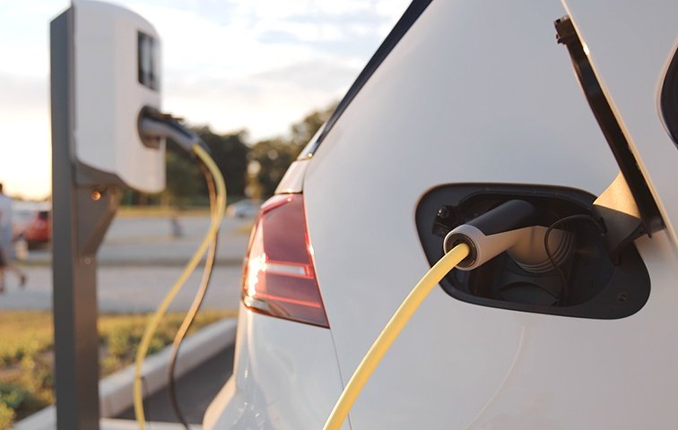
“Why does the same charger work fine with Vehicle A but trip with Vehicle B?” “Why does it charge at low power but fault at high power?” “Why can’t we pass the A0° certification test?” — These are the soul-searching questions that EV charger manufacturers frequently encounter during R&D testing.
What’s more challenging is that these phenomena are often “intermittent”: the portable charging cable (IC-CPD) works normally, but the wallbox charger triggers protection; most vehicles charge without issues, but a few specific models repeatedly fault. Customers’ first reaction is often “insufficient sensor accuracy” or “product mismatch,” but the truth usually lies deeper in the electrical characteristics.
[Technical Analysis] The Secret Behind Leakage Current Waveforms
To understand these issues, we need to recognize the “true face” of EV charger leakage currents. Under normal conditions, leakage current presents as a smooth AC sine waveform. But when the On-Board Charger (OBC) malfunctions, the leakage current waveform undergoes bizarre changes:
Phase One: Latent Period with Stable AC — Early in charging, the leakage current waveform is normal with amplitude within safe thresholds.
Phase Two: Deterioration with Waveform Distortion — As OBC internal components age or fail, leakage current gradually increases and the waveform begins to distort.
Phase Three: Collapse with High-Frequency Pulses — When the fault progresses to a certain level, high-frequency pulse interference signals appear in the leakage current, synchronized with the power frequency (50Hz/60Hz) at approximately 20ms intervals. Electrically, this waveform resembles a pulsating DC after half-wave rectification (A0° wave).
Key Insight: These high-frequency pulses are not random noise but characteristic signals of OBC internal rectifier circuit failure. Portable chargers operate at lower power (typically 3.5kW/16A), so leakage currents don’t reach trigger thresholds; high-power wallbox chargers (7kW/32A) amplify the fault, causing protection trips.
[Trap] A0° Testing: The “Hidden Pit” in Circuit Design
IEC 62955 and UL 2231 standards mandate residual current detection (A0°) as a safety requirement. However, many manufacturers encounter mysterious phenomena during certification: the sensor passes standalone testing, but the A0° threshold drops unexpectedly when integrated into the complete system.
The root cause lies in circuit design positioning. The A0° wave is essentially pulsating DC after half-wave rectification. If detection circuits (such as rectifier diodes + optocouplers) are placed downstream of the sensor copper terminals, the detection current flows through the sensor’s magnetic core along with the terminals, creating “phantom” readings that offset the threshold.
Simulation verification shows: When the rectifier diode operates normally, it produces unidirectional threshold offset; when the diode fails (such as during 2.5kV withstand voltage testing), the waveform becomes sinusoidal, causing bidirectional threshold offset — this matches field measurement data perfectly.
[Design Recommendations] How to Avoid the Pitfalls
Based on the above analysis, three recommendations for EV charger R&D engineers:
- Keep the “Clean Zone” Behind Sensors — Do not place additional circuits downstream of residual current sensors. Ideally, connect directly to relays and associated circuits only. Position detection circuits upstream to ensure they don’t pass through the sensor’s magnetic core.
- Component Selection with Margin — Rectifier diode withstand voltage must exceed 2.8kV (such as 1N5399, rated 3kV) to pass system-level 2.5kV withstand testing. Parallel a 4148 diode at the optocoupler front-end as reverse voltage protection.
- Faulty Vehicle Identification — When users report “low-power charging works but high-power faults,” recommend OBC inspection rather than simply replacing the charger.
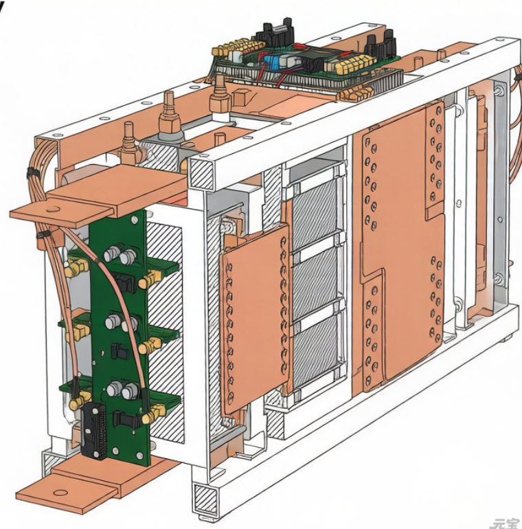
[MAGTRON Solution] RCMU101SM Series: Born for Global Standards
Addressing these industry pain points, MAGTRON introduces the RCMU101SM series of residual current sensors, specifically designed for EV charging infrastructure:
- iFluxgate® Technology: Self-developed SoC chip integrating self-check functionality and logic judgment, 2% accuracy, zero drift <0.5%FS
- Full Waveform Detection Capability: Precisely identifies Type A, Type B, and DC pulsating residual currents (A0°/A90°/A180°), response time <30ms
- Modular Integration: Combined metering and residual current detection in one package, single power supply, voltage/switch output options
- Global Standards Ready: Compliant with IEC 62955, UL 2231, and regional standards; certified by CE, UL, TÜV, DEKRA, SGS
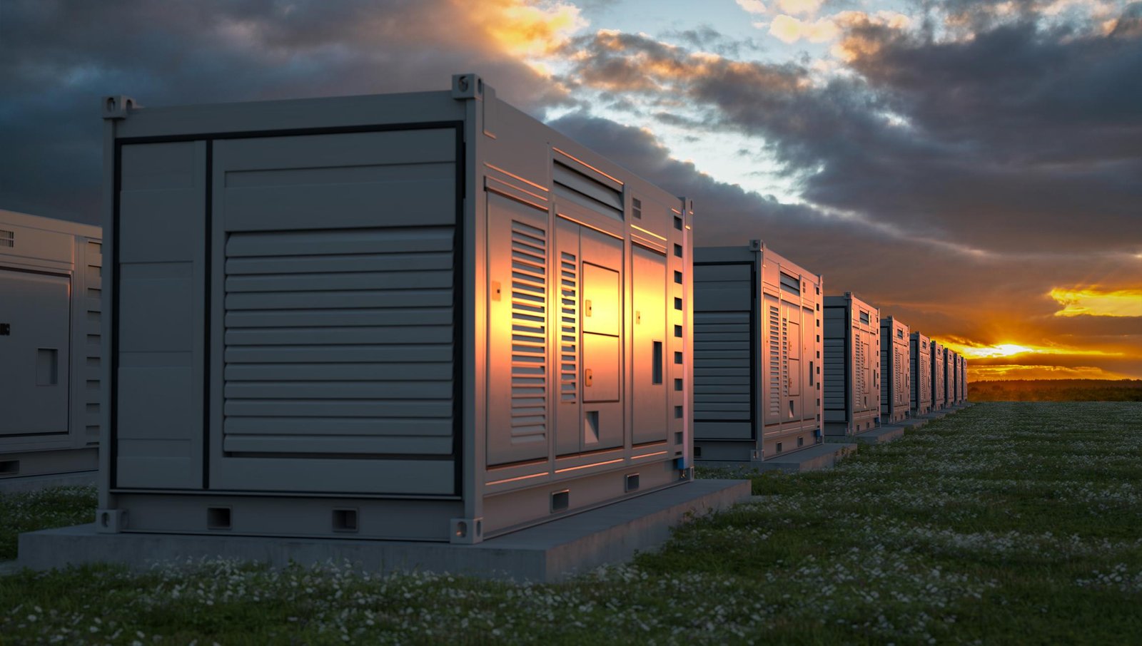
Typical applications include 7kW AC wallboxes, portable chargers (IC-CPD), 120kW DC fast chargers, and energy-storage-integrated charging stations. The series has been mass-delivered to leading EV charger manufacturers with over 10 million cumulative operating hours.
Residual current protection in EV chargers has never been a simple “check-box” configuration. It is a systematic engineering effort concerning user safety, product compliance, and brand reputation. As IEC and UL standards continue evolving worldwide, proactively deploying highly reliable residual current detection solutions is mandatory homework for every EV charger manufacturer.