In high-frequency power electronics systems dominated by SiC/GaN wide-bandgap devices, the bandwidth, transient response, and phase characteristics of current sensors are critical factors that determine control loop stability, protection reliability, and overall system efficiency. The rule-of-thumb from the IGBT era—“bandwidth is good enough”—has become one of the most overlooked sources of failure in high-frequency systems.
I. Establishing the Right Baseline: Clarifying Core Metrics
Most selection mistakes stem from unclear understanding of the definition boundaries and physical relationships of key parameters. All discussions in this article are based on standard engineering definitions in power electronics and fundamental linear control theory. Let’s first align on four essential concepts:
-3 dB Bandwidth
The frequency at which the sensor output amplitude drops to 70.7% (-3 dB) of its low-frequency reference value. It defines the upper limit of the sensor’s linear measurement range—not the end of its “usable bandwidth.”
Step Response and Response Time
The speed at which a sensor reacts to a sudden step change in current. In engineering practice, it is typically defined as the rise time from 10% to 90% of the steady-state value. This is a critical lower-bound metric for overcurrent protection.
Phase Response and Group Delay
Phase response describes the phase shift introduced by the sensor at different frequencies. Group delay, the derivative of phase response, reflects the consistency of signal transmission delay across frequencies and is a key factor affecting control loop stability.
Intrinsic Relationship Between Bandwidth and Response Time
For 99% of linear time-invariant (LTI) minimum-phase current sensors on the market, bandwidth and rise time follow a strict theoretical relationship:
tr ≈ 0.35 / fBW
(where tr is rise time and fBW is the -3 dB bandwidth)
Bandwidth is a necessary but not sufficient condition for transient performance. Insufficient bandwidth guarantees poor response speed; however, even with sufficient bandwidth, non-ideal factors such as filtering, parasitics, and compensation delays can still cause overshoot, oscillation, or excessive delay.
Based on this, we define two key application boundaries:
- Steady-state closed-loop control & high-precision measurement: focus on bandwidth and amplitude/phase response
- Transient short-circuit protection: focus on step response time and total signal chain delay
II. Why Sensor Selection Logic Must Be Fundamentally Rebuilt
Selection strategies from the IGBT era were well-suited to their time. However, three fundamental shifts introduced by SiC/GaN devices have completely invalidated those assumptions, turning them into hidden risks in high-frequency systems.
1. Switching Behavior Shift: Orders-of-Magnitude Increase in di/dt and Frequency
IGBTs typically operate at di/dt of 5–10 A/μs and switching frequencies of 10–20 kHz. In contrast, SiC/GaN devices reach 50–200 A/μs, with commercial switching frequencies commonly at 100 kHz and some GaN designs exceeding MHz levels.
Key challenge:
Sharp current edges now last only a few hundred nanoseconds, and switching waveforms contain significant higher-order harmonics (3rd, 5th, etc.). Sensors with insufficient bandwidth will smooth these edges and attenuate high-frequency components, leading to loss of peak current information and severe waveform distortion—ultimately causing overcurrent protection failure.
2. Control Loop Evolution: Phase Delay Becomes Critical
In the IGBT era, current loop bandwidth was typically 1–2 kHz, and sensor-induced phase delay (<5°) was negligible. With SiC/GaN systems pushing loop bandwidths to 5–20 kHz, sensor phase delay has become a dominant factor in loop stability.
Key challenge:
If the sensor plus signal chain introduces more than 30° phase shift at loop bandwidth, phase margin becomes insufficient, leading to oscillations, increased ripple, and even permanent damage to power devices.
3. Narrower Reliability Margins: Shorter Short-Circuit Withstand Time
IGBTs can typically withstand short circuits for >10 μs, providing ample protection window. In contrast, industrial and automotive-grade SiC MOSFETs can only withstand 3–5 μs, with some high-voltage devices below 2 μs.
Key challenge:
The total response time of the sensor plus protection circuit must be less than half of the short-circuit withstand time. Sub-microsecond response is no longer a luxury—it is a baseline requirement. Sensors with 3–10 μs response time (common in the IGBT era) are effectively unusable in this context.
III. Five Common Pitfalls in Sensor Selection
Pitfall 1: Treating -3 dB Bandwidth as Usable Bandwidth
Misconception:
Either assuming signals at -3 dB are unusable, or blindly applying rules like “sensor bandwidth must be 5–10× switching frequency.”
Reality:
Usable bandwidth depends entirely on application requirements; -3 dB is a reference point, not a cutoff.
Correct approach:
- High-precision measurement: attenuation <1 dB
- Closed-loop control: attenuation <3 dB, bandwidth ≥ 5–10× loop bandwidth
- Harmonic monitoring: bandwidth ≥ 3–5× switching frequency
- Overcurrent protection: bandwidth can exceed -3 dB limit; response time is key
Pitfall 2: Assuming High Bandwidth Equals Fast Transient Response
Misconception:
If bandwidth meets spec, transient performance is assumed adequate.
Reality:
Bandwidth describes steady-state frequency response, not transient behavior. Non-idealities can still cause overshoot, oscillation, or delay.
Correct approach:
- Bandwidth is necessary but insufficient
- Always verify step response and total signal chain delay
Pitfall 3: Ignoring Phase Response and Group Delay
Misconception:
Flat amplitude response implies good performance.
Reality:
Phase distortion and group delay can silently degrade control loop stability.
Correct approach:
- For loop bandwidth ≥5 kHz, evaluate total phase shift
- Typical RC/Butterworth filters introduce ~22° phase shift at 1/5 cutoff frequency
- Total phase shift >40° at loop bandwidth risks oscillation
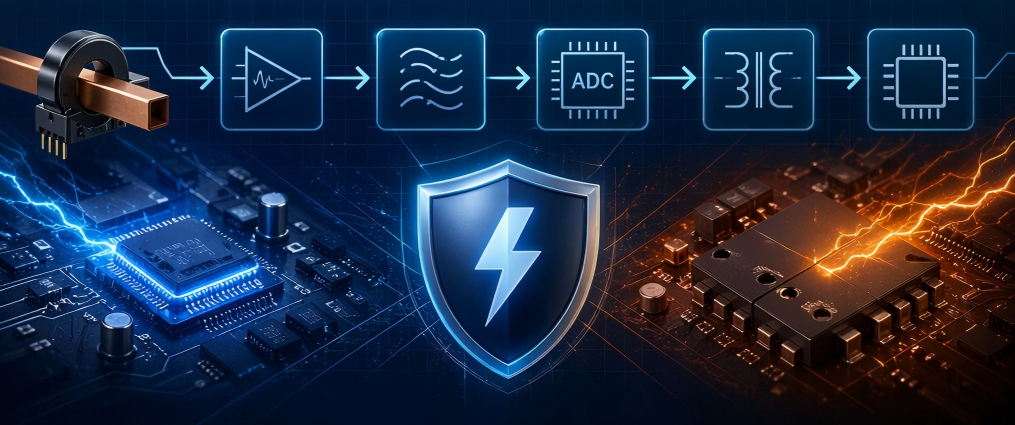
Pitfall 4: Ignoring the Entire Signal Chain
Misconception:
Selection is based solely on sensor datasheet specs.
Reality:
System performance is limited by the weakest link in the signal chain.
Correct approach:
- Evaluate sensor + cable + conditioning + ADC + isolation as a whole
- Pay special attention to Σ-Δ modulators, which can introduce tens of μs group delay
Pitfall 5: Confusing DC and AC Measurement Requirements
Misconception:
Only bandwidth and response time matter.
Reality:
Different technologies have fundamental measurement limitations.
Correct approach:
First determine whether the signal is DC, AC, or both, then eliminate incompatible technologies before evaluating performance.
IV. Technology Landscape: Capabilities and Application Boundaries
| Technology | Bandwidth (-3 dB) | Step Response | Capability | Key Characteristics |
|---|---|---|---|---|
| Open-loop Hall | 50 kHz–300 kHz | 3–10 μs | DC + AC | Low cost, low power, limited performance |
| Closed-loop Hall | 200 kHz–1.5 MHz | 0.5–1 μs | DC + AC | High bandwidth, good linearity |
| TMR/GMR | 500 kHz–2 MHz | 100–500 ns | DC + AC | Ultra-fast, high bandwidth, low power |
| Fluxgate | DC–1 MHz | 0.5–2 μs | DC + AC | उत्कृष्ट DC accuracy, low drift |
| Shunt + Isolation Amp | 100 kHz–10 MHz+ | Depends | DC + AC | Unlimited bandwidth, no hysteresis |
| Rogowski Coil | 10 kHz–20 MHz+ | <100 ns | AC only | No insertion loss, requires integrator |
| Current Transformer (CT) | 50 Hz–1 MHz | <1 μs | AC only | Good isolation, low cost |
Selection Guidelines:
- Low-frequency IGBT: open-loop Hall
- Mid/high-frequency SiC: closed-loop Hall or TMR
- Ultra-high-frequency GaN (>500 kHz): TMR or shunt + high-speed isolation
- High-precision DC: fluxgate or shunt
- Grid-side AC: Rogowski coil or CT
V. Application-Specific Selection Guidelines
1. Servo Drives & Motor Control
Requirements: loop stability, ripple monitoring, fast protection
Criteria: bandwidth ≥ 5–10× loop bandwidth; response time ≤ 1/2 protection time
- Low frequency (<40 kHz): open/closed-loop Hall (≥100 kHz)
- High performance (>80 kHz): closed-loop Hall or TMR (≥500 kHz, <1 μs)
2. Grid-Tied Inverters (PV / Energy Storage)
Requirements: THD compliance, DC control, synchronization
- Small systems: shunt + isolation amp / fluxgate
- Large systems: closed-loop Hall / TMR
- Grid AC: Rogowski coil / CT
3. DC Fast Charging / Energy Storage PCS
Requirements: DC accuracy, fast protection, wide dynamic range
- DC bus: shunt / fluxgate / closed-loop Hall
- Output: closed-loop Hall / TMR
4. Ultra-High-Frequency SiC/GaN Power Supplies (>500 kHz)
Requirements: ultra-high bandwidth, ultra-fast response, minimal phase delay
Criteria: bandwidth ≥ 3× switching frequency; response time <500 ns
- Recommended: TMR/GMR or shunt + hig
VI. Selection Checklist and System-Level Validation
Pre-selection checklist:
- Define measurement type: DC, AC, or both
- Identify application: control, measurement, or protection
- Determine key specs: loop bandwidth, switching frequency, max harmonic, allowable delay
- Select appropriate technology
- Evaluate full signal chain performance
- Verify accuracy within operating frequency range
Conclusion
The adoption of SiC/GaN devices is pushing power electronics fully into the high-frequency domain. Current sensors are no longer peripheral components—they are critical front-end elements in both control and protection paths.
Abandon legacy IGBT-era assumptions. Take a system-level approach: start from application requirements, match bandwidth, response, and phase characteristics accordingly, and validate performance through real measurements. This is the foundation for achieving high reliability in modern high-frequency power electronics systems.